In the kinematic chain of the manipulator of the hydraulic excavators, the drive of the revolute pairs is carried out by a hydraulic cylinder jointed to the both links of the pair, which realizes a planar drive mechanism of the type - Inverted Slider-Crank Mechanism, centric type (ISCM). The power capabilities of the ISCM are described by the basic transfer function of the mechanism dS/dφ, which fully describes the driving moment of the ISCM in dimensionless form. The synthesis of this mechanism begins with a preliminary choice of the small parameter λ=R/L<1, equal to the ratio of the lengths of the links of the ISCM revolute pair. The synthesis then proceeds in a few steps. First, the two moment functions are fitting - the moment of the external forces and the driving moment of the hydraulic cylinder, respectively in their dimensionless form. So that for the entire considered range of ISCM, the driving moment of the hydraulic cylinder must be greater than the external moment. In this stage, all the angles of the mechanism are fully determined, as well as the coefficient K, which converts the external moment into a dimensionless form. This is followed by next step in which the cylinder force F and the ISCM metric - the lengths R and L of the rotary pair links, are determined. However, here the coefficient K=F.R defines the two unknowns in a product, which means that by choosing a standard cylinder force Fo, the dimension R is calculated from the above relation. This can be repeated several times until acceptable mechanism dimensions and a suitable cylinder are obtained. Several examples of the described synthesis are given: an external moment with equal values at both ends of the considered range and an external moment from the forces of gravity. Of course, optimization procedures can be performed at various points in the synthesis procedure.
The relative rotation of two jointed links of the kinematic chain of the manipulator of the hydraulic excavator is carried out by a driving hydraulic mechanism. It is realized by a hydraulic cylinder hinged to the above-mentioned two links, this way a planar drive mechanism of the type Inverted Slider-Crank Mechanism, centric type (ISCM) is obtained.
These mechanisms - ISCM, are widely used in the practice. They are included in the kinematic schemes of automatic devices 1, industrial robots 2, 3, construction machines, loaders, hydraulic excavators 4, 5, 6, 7, etc. Unlike the slider-crank mechanism, here the sliding pair (hydraulic cylinder) is the drive. These mechanisms are characterized by great power capabilities, simple structure and high reliability.
Usually one to three such ISCM mechanisms are included in the mentioned kinematic chains. For example, the kinematic chain of the manipulator of hydraulic excavators includes several rigid links connected with revolute pairs and driven one to another by hydraulic cylinders, connected to the links by revolute pairs 8, 9. This way the chains with several ISCM mechanisms are formed, arranged sequentially. Thus, in order to study these complex kinematic chains, the properties of the constituent mechanism must be well known. In 10 the transfer functions of ISCM are well described.
ISCM synthesis tasks typically involve three to five parameters to determine – cylinder force, dimensions, and angles. In 11, the synthesis problem is solved using infinitely close positions with three transfer functions and gives the exact solution. Optimization tasks are also most often solved with consideration of external forces. In 12, a two-criteria optimization problem is solved with a constant external moment and considering the inertial load. In 13 the multi-criteria decision approach is used for the optimal synthesis of loader drive mechanisms. Another paper 14 reports the optimization synthesis of a hydraulically actuated drive mechanism of excavators. The defined multiobjective optimization task is considered as a mixed variable nonlinear constrained optimization problem containing 5 continuous and 2 discrete variables. Using Monte Carlo method, several Pareto-optimal compromise solutions are obtained. In 15 optimal synthesis of manipulator drive mechanisms of multibody chain of hydraulic excavator on the basis of tribological criterion is carried out. Other research 16 identifies the excavator's capability to generate needed digging force in hexahedral polygon space. Optimum dimensional synthesis of the working mechanism is finished by using the genetic algorithm to solve the established optimization problem.
The present work aims to consider the synthesis of the drive mechanism of hydraulic excavators, type ISCM with hydraulic cylinder, taking into account the specific force characteristics of the ISCM, with an analytical solution supported by a graphical representation.
We consider ISCM synthesis in the following setting: A heavy body is set rotating around the point О in the Oxy plane, and its position is determined by a characteristic axis ОС, forming an angle ψ with the Ox axis. The drive of the OC body is carried out by a hydraulic cylinder AB, so that point A is stationary, and point B is hingedly connected to the OC body. Thus, an ISCM-type mechanism is formed, with the revolute pair AOB driven by the hydraulic cylinder AB. An external/technological moment T(ψ) acts on the body OC, which can include both the moment of weight and the moment of technological forces (see Figure 1).
The following parameters nomenclature is used:
R=OA, L=OB – lengths of the links of the rotation pair AOB, as R<L;
λ – a small parameter, characteristic of ISCM, defined as:
 | (1) |
ψ – the angle considering the position of the heavy link ОС relative to the Оx axis;
φ – the ISCM angle (of the rotation pair AOB);
S = BA - the variable distance between the joints A and B of the cylinder (stroke of the cylinder);
f(φ)=dS/dφ – basic transfer function of ISCM;
F – the force of the hydraulic cylinder;
h(φ) – arm of the force F relative to point O;
MF(φ) – driving moment of the force of the cylinder relative to the point O;
T(ψ) –external/technological moment;
α – angle of the fixed link OA relative to the axis Оx;
β – angle between lines OC and OB;
ψ1 and ψ2 – set the rotation range of the OC body;
φ1 and φ2 – set the range of movement of the ISCM, where it is obvious:
 | (2) |
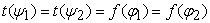
The relationship between the angles ψ and φ is given by
 | (3) |
where the total angle γ is essential for the calculations, and its distribution as α and β is determined by the final design layout of the mechanism.
2.2. The Synthesis TascThe task is to synthesize an ISCM mechanism, rotating the link OC between two end positions determined by the angles ψ1 and ψ2, at a given external/technological moment T(ψ) relative to point O - in the range ∆ψ = ψ2 – ψ1. The moment of the external forces T(ψ) can be set either as a function of the angle ψ or with point values in the range ∆ψ. It is assumed that the end position values T(ψ1) and T(ψ2) are known. The motions are assumed to be slow and no inertial forces are taken into account.
It is obvious that the moment of the force of the cylinder relative to point O must be greater than or equal to the external/technological moment for the entire considered range ∆ψ.

The driving moment of the force of the cylinder F relative to point O is defined in the entire working range of the angle φ (0-180o), in the form 10:
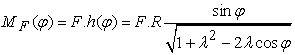 | (4) |
Dividing (4) on the coefficient K=F.R, the moment of force of the cylinder MF(φ) can be reduced to the following dimensionless form - f(φ):
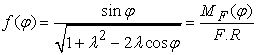 | (5) |
From other side f(φ) is the known dimensionless transfer function dS/dφ of the ISCM, which fully describes the power capabilities of the mechanism 10.
To be determined: the end positions angles φ1 and φ2 defining the range of motion of the ISCM, the total angle γ, the dimensions R and L of the mechanism, and the force of the cylinder F.
Considering (2), (3) and (5) we have 4 unknowns – the small parameter λ, the angle φ1 (or φ2), the angle γ and cofficient K=F.R.
At the beginning of the synthesis task, the characteristic of ISCM - small parameter λ must be chosen. Usually, the small parameter λ varies between 0,2 and 0,5. A smaller parameter λ results in a more compact mechanism but with a smaller driving moment MF(φ), and a larger parameter λ leads to larger dimensions and a larger driving moment MF(φ). Of course, after varying the values of the small parameter λ, several solutions can be obtained and the optimal solution can be sought.
3.2. Fitting of the External Moment T(ψ) to the Moment of the Cylinder Force MF(φ) in the Range ∆ψFor the entire operating range ∆ψ, the cylinder force moment MF(φ) must be greater than the external technological moment T(ψ). I.e. the condition must be met:
 | (6) |
where  and
and 
We divide equation (6) by F.R and reduce it to a dimensionless form:
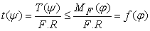 | (7) |
I.e. external dimensionless moment function t(ψ) must fit the function f(φ) without exceeding it, for the whole range ∆ψ. This is achieved by normalizing the moment T(ψ), by dividing it by the coefficient K=F.R and with phase shift on the angle γ along the horizontal axis of the two functions - f(φ) relative to t(ψ).
In the most general case we will consider, the external moment t(ψ) and the function f(φ) must have two common points at both ends of the interval ∆ψ. (see Figure 2). That is, the conditions must be met here:
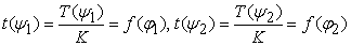 | (8) |
where K=F.R and, of course, condition (7) is fulfilled for the entire range ∆ψ.
3.3. Determining the Angles of ISCM MechanismAll angles are defined here. Angles ψ1 and ψ2 are set, angles γ, φ1 and φ2 are subject to determination.
We divide the first equation of (8) by the second and get:
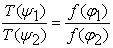 | (9) |
And after using (5) and relations coming from (3):
 | (10) |
we arrive at an equation with one unknown, the angle γ:
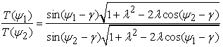 | (11) |
Equation (11) can be solved by numerical methods.

After the determination of the angle γ from (11) follows the determination of the end position angles φ1 and φ2 of the ISCM, from the equations (10).
With the completion of this stage, the geometry of the considered mechanism is essentially ready, once we know the parameter λ and the angles φ1 and φ2. It remains to determine the dimensions of the mechanism and the force of the cylinder.
3.4. Determination of Cylinder Force and ISCM DimensionsThe coefficient K is determined by the one of equation of (8), for example, as:
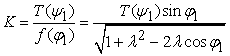 | (12) |
The cylinder force F and the ISCM dimension R are defined as the product:
 | (13) |
We can choose standard cylinder with force Fo. Then for the dimensions of the links AO and OB we get:
 | (14) |
Several selections of a standard cylinder force Fo may be required until appropriate mechanism dimensions R and L are obtained, also an optimization can be done. Choosing big cylinder with bigger force Fo, leads to less dimensions of ISCM. In the opposite case choosing small cylinder leads to bigger dimensions of the mechanism.
The last step is to check the stroke performation of the cylinder. It is checked whether the selected cylinder has the required stroke 11:
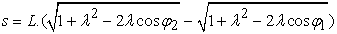 | (15) |
With this, the ISCM synthesis task is fully complete: at set end position angles ψ1 and ψ2, and the function of the external moment T(ψ); with a small parameter λ chosen. In the described algorithm, the following are obtained: the dimensions of the mechanism R and L; the angle γ, which is distributed as a sum of two angles – α and β, distributed for design reasons; the end position angles of ISCM – φ1 and φ2 and the force of the hydraulic cylinder Fo.
Here, the external moment has equal values at both ends of the considered interval ∆ψ:
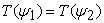 | (16) |
So, from (8) and (9) it’s clear that:
 | (17) |
Here we can list the following cases (see Figure 3):
a. Constant moment – ta(ψ)=const, for example in clamping devices, some grippers, etc.
b. Moment in case of cubic functions.
c. Moment in complex trigonometric functions as in some grippers etc.
Of course, condition (7) must be fulfilled for the entire operating range ∆ψ.
Considering that f(φ1)=f(φ2), we have next equation:
 | (18) |
The angles φ1 and φ2 consider (2) can be determined from here mostly by numerical methods. And taking into account relations (10), we can determine the angle γ.
Equation (18) can also be transformed into the form:
 | (19) |

After calculation of the coefficient K from (12) and the choice of the cylinder force Fo, - the parameters Fo, R and L can be determined from (14), as it is explained in p.3.4. This case has very good geometric representation (see Figure 3).
4.2. Example 2 – External Moment of Gravity ForcesLet us assume that the forces of gravity applied to the body OC are reduced to one force - the weight G, applied at point C. Then the external moment takes the form:
 | (20) |
where ψ1 ≤ ψ ≤ ψ2.
In this case, the external moment T(ψ) is a pure cosine function, and the cylinder moment - MF(φ), is a function close to the sine. Then the solution should be sought by matching the maximum values of these two functions, that is, in the area of the angle γ= -90°. Here the condition (7) takes the form:
 | (21) |
where the new one coefficient KG is:
 | (22) |
Here the product (13) то determine the force F and the dimension R takes the form:
 | (23) |
Thus, the solution of the ISCM synthesis problem essentially depends on the values of the end position angles of the external moment - ψ1 and ψ2, that is, on the location of the range Δψ. So the solution of this case is going acc to the algorithm described in points 3.1, 3.2, 3.3 and 3.4.
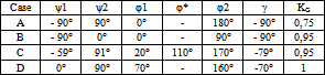
Next 4 cases covering one half of the cosine function with weight moment variation from zero to maximum and back to zero are considered:
Case A. Maximum range Δψ. The end poition angles are:
ψ1= –90°, ψ2= 90°, Δψ=180°
Case B. Half down range. The end poition angles are:
ψ1= –90°, ψ2= 0°, Δψ=90°
Case C. Arbitrary intermediate range. The end poition angles are: ψ1= -59°, ψ2= 91°, Δψ=150°
Case D. Half upper range. The end poition angles are:
ψ1= 0°, ψ2= 90°, Δψ=90°
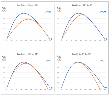
Table 1 shows the obtained solutions for the four cases. Here with φ* we mark the value of the angle φ at which we have a common point and a common tangent between the two functions. Figure 4 shows the graphs of the four solutions.
The Inverted Slider-Crank Mechanism (ISCM) with a hydraulic cylinder is the main drive mechanism of the manipulator of hydraulic excavators. The synthesis of this mechanism is most often performed with optimization tasks with different number of variables, under different criteria and optimization methods. The present work aims to describe the characteristic force properties of ISCM driven by hydraulic cylinder, and this way to create a simplified synthesis algorithm accounting force conditions. The power capabilities of the ISCM are fully described by the basic transfer function dS/dφ of the mechanism, which describes the driving moment in dimensionless form. The proposed algorithm uses the diagram of the mechanism transfer function dS/dφ, relative to which the moment of the external forces is fitted, so that for the entire range considered, the moment of the hydraulic cylinder must be greater than the external moment. This is a very convenient method for the synthesis, because the solutions are visualized graphically and within the graph of the main transfer function dS/dφ of the mechanism. Also, the diagram of the mentioned transfer function depends only on the parameter λ, and of course from the angle φ defining ISCM in the range 0-180°. So, in case of preliminary choice of the parameter λ, we can drаw the transfer function dS/dφ, which defines the driving moment, and we can start the synthesis of ISCM, described in this work. Of course, optimization procedures can be carried out at different stages of the synthesis procedure, or as complete optimization task, with a view to achieving optimal results.
| [1] | Myszka D., Machines and mechanisms: applied kinematic analysis-4th ed. Pearson Education, Inc., publishing as Prentice Hall, 2012. | ||
| In article | |||
| [2] | Bu F. and Yao B., “Nonlinear model based coordinated adaptive robust control of electro-hydraulic robotic arms via overparametrizing method”. February 2001, in - IEEE International Conference on Robotics and Automation 4: Proceedings, 3459-3464, vol. 4. | ||
| In article | |||
| [3] | Valdiero A., Guenther R., De Pieri E. and Negri V. (2013). “Cascade Control of Hydraulically Driven Manipulators With Friction Compensation”. International Journal of Fluid Power, March 2007, 8(1):7-16. | ||
| In article | View Article | ||
| [4] | Hao W., “Analysis report of 2010 excavator market in China,” Construction Machinery Technology & Management, vol. 2, article 23, 2011. | ||
| In article | |||
| [5] | Ni T., Zhang H, Yu C., Zhao D. and Liu S., “Design of highly realistic virtual environment for excavator simulator”. Computers and Electrical Engineering, vol. 39, no. 7, pp. 2112-2123, 2013. | ||
| In article | View Article | ||
| [6] | Xu J. and Yoon H-S., “A Review on Mechanical and Hydraulic System Modeling of Excavator Manipulator System”. Journal of Construction Engineering. Volume 2016, Article ID 9409370. | ||
| In article | View Article | ||
| [7] | Gnasa U., Thielecke K., Modler K-H. and Richter E-R., “Design and development of a hydraulic manipulator with mechanism/Pro”. International ADAMS users’ Conference, Berlin, 17-18 Nov 1999. | ||
| In article | |||
| [8] | Mitrev R., “Web Based Enviroment for Design and Analysis of Hydraulic Escavator”. Journal of Multidisciplinary Engineering Science and Technology (JMEST), Vol. 2, Issue 12, December 2015. | ||
| In article | |||
| [9] | Patel D., Patel B. and Patel M., “A Critical Review on Kinematics of Hydraulic Excavator Backhoe Attachment”. Int. J. Mech. Eng. & Rob. Res. Vol. 4, No. 2, April 2015. | ||
| In article | |||
| [10] | Ganchev K., “Inverted Slider-Crank Mechanism Driven by Hydraulic Cylinder: Transfer Functions and Approximations”, Engineering Mathematics. Volume 6, Issue 1, June 2022, pp. 1-5. | ||
| In article | |||
| [11] | Ganchev K., “Synthesis of Slider-Crank Mechanism Driven by Hydraulic Cylinder”. Mechanika na Mashinite, 34/2001, pp. 75-95. | ||
| In article | |||
| [12] | Koev P. and Vitliemov V., “Тwo-Criterion Optimization Kinematic Synthesis of Slider-Crank Mechanism”. Mechanika na Mashinite, vol.5 (20), 4/1997, pp.30-34. | ||
| In article | |||
| [13] | Petrovic G., Pavlovic J., Madic M. and Marinkovic D., “Optimal Synthesis of Loader Drive Mechanisms: A Group Robust Decision-Making Rule Generation Approach”. Machines 2022, 10(5), 329. | ||
| In article | View Article | ||
| [14] | Mitrev R. and Todorov T., “Multicriteria Optimal Selection of a Hydraulic Cylinder for Drive Mechanisms”. FME Transactions, 49/2021, 501-510. | ||
| In article | View Article | ||
| [15] | Pavlovic J., Janosevic D. and Jovanovic V., “Optimization of manipulator drive mechanisms of hydraulic excavators on the basis of the tribological criterion”. Scientia Iranica, B (2020), 27(5), 2372-2381. | ||
| In article | |||
| [16] | Zou Z., Chen J. and Pang X., “Optimum dimensional synthesis for the working mechanism of a hydraulic excavator to improve the digging performance”. SAGE journals, Oct.2017. | ||
| In article | View Article | ||
Published with license by Science and Education Publishing, Copyright © 2022 Krasimir Ganchev
![]() This work is licensed under a Creative Commons Attribution 4.0 International License. To view a copy of this license, visit
http://creativecommons.org/licenses/by/4.0/
This work is licensed under a Creative Commons Attribution 4.0 International License. To view a copy of this license, visit
http://creativecommons.org/licenses/by/4.0/
| [1] | Myszka D., Machines and mechanisms: applied kinematic analysis-4th ed. Pearson Education, Inc., publishing as Prentice Hall, 2012. | ||
| In article | |||
| [2] | Bu F. and Yao B., “Nonlinear model based coordinated adaptive robust control of electro-hydraulic robotic arms via overparametrizing method”. February 2001, in - IEEE International Conference on Robotics and Automation 4: Proceedings, 3459-3464, vol. 4. | ||
| In article | |||
| [3] | Valdiero A., Guenther R., De Pieri E. and Negri V. (2013). “Cascade Control of Hydraulically Driven Manipulators With Friction Compensation”. International Journal of Fluid Power, March 2007, 8(1):7-16. | ||
| In article | View Article | ||
| [4] | Hao W., “Analysis report of 2010 excavator market in China,” Construction Machinery Technology & Management, vol. 2, article 23, 2011. | ||
| In article | |||
| [5] | Ni T., Zhang H, Yu C., Zhao D. and Liu S., “Design of highly realistic virtual environment for excavator simulator”. Computers and Electrical Engineering, vol. 39, no. 7, pp. 2112-2123, 2013. | ||
| In article | View Article | ||
| [6] | Xu J. and Yoon H-S., “A Review on Mechanical and Hydraulic System Modeling of Excavator Manipulator System”. Journal of Construction Engineering. Volume 2016, Article ID 9409370. | ||
| In article | View Article | ||
| [7] | Gnasa U., Thielecke K., Modler K-H. and Richter E-R., “Design and development of a hydraulic manipulator with mechanism/Pro”. International ADAMS users’ Conference, Berlin, 17-18 Nov 1999. | ||
| In article | |||
| [8] | Mitrev R., “Web Based Enviroment for Design and Analysis of Hydraulic Escavator”. Journal of Multidisciplinary Engineering Science and Technology (JMEST), Vol. 2, Issue 12, December 2015. | ||
| In article | |||
| [9] | Patel D., Patel B. and Patel M., “A Critical Review on Kinematics of Hydraulic Excavator Backhoe Attachment”. Int. J. Mech. Eng. & Rob. Res. Vol. 4, No. 2, April 2015. | ||
| In article | |||
| [10] | Ganchev K., “Inverted Slider-Crank Mechanism Driven by Hydraulic Cylinder: Transfer Functions and Approximations”, Engineering Mathematics. Volume 6, Issue 1, June 2022, pp. 1-5. | ||
| In article | |||
| [11] | Ganchev K., “Synthesis of Slider-Crank Mechanism Driven by Hydraulic Cylinder”. Mechanika na Mashinite, 34/2001, pp. 75-95. | ||
| In article | |||
| [12] | Koev P. and Vitliemov V., “Тwo-Criterion Optimization Kinematic Synthesis of Slider-Crank Mechanism”. Mechanika na Mashinite, vol.5 (20), 4/1997, pp.30-34. | ||
| In article | |||
| [13] | Petrovic G., Pavlovic J., Madic M. and Marinkovic D., “Optimal Synthesis of Loader Drive Mechanisms: A Group Robust Decision-Making Rule Generation Approach”. Machines 2022, 10(5), 329. | ||
| In article | View Article | ||
| [14] | Mitrev R. and Todorov T., “Multicriteria Optimal Selection of a Hydraulic Cylinder for Drive Mechanisms”. FME Transactions, 49/2021, 501-510. | ||
| In article | View Article | ||
| [15] | Pavlovic J., Janosevic D. and Jovanovic V., “Optimization of manipulator drive mechanisms of hydraulic excavators on the basis of the tribological criterion”. Scientia Iranica, B (2020), 27(5), 2372-2381. | ||
| In article | |||
| [16] | Zou Z., Chen J. and Pang X., “Optimum dimensional synthesis for the working mechanism of a hydraulic excavator to improve the digging performance”. SAGE journals, Oct.2017. | ||
| In article | View Article | ||


