 sciepub.com
 Quick Submission

Investigation of Stress Formation and Wear Effect of Tool by Finite Element Simulation
Aung Kyaw Sein1, , Ei Ei Htwe1, Nyein Aye San1
1Department of Mechanical Engineering, Mandalay Technological University, Myanmar
Abstract
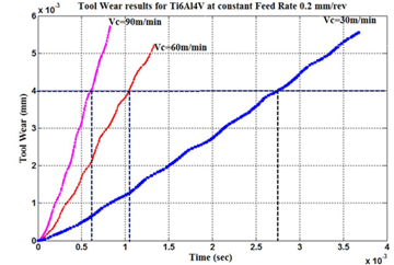
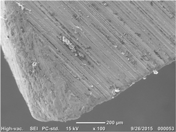
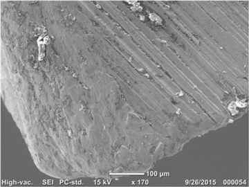
The paper presents aspects related to simulation of metal cutting for titanium and its alloys. Detailed study on progression and wear mechanism at the cutting edge of carbide tools were carried out at cutting speed of 30, 60 and 90 m/min, feed rate of 0.2 mm/rev. Firstly, milling finite element model is given based on orthogonal cutting principle, and then the influence laws of cutting parameters on chip formation are analyzed by using different simulation parameters. For simulations, the software based on finite element method DEFORM 2D was used. Machining simulations were conducted using Ti6Al4V and uncoated carbide for workpiece and tool material respectively. DEFORM 2D, a widely used software tool employed for modelling and simulating the orthogonal machining process with different cutting speeds and feed rates. The pattern of wear progression on the flank face of the carbide tools consist of three stages for all the cutting speed simulated. Wear mechanism such as abrasive and adhesive wear were observed on the flank face. Crater wear due to diffusion was also observed on the rake race. The flank wear results most commonly from abrasion on the cutting edge of the tool. The maximum land width is used as an indication of the extent of the flank wear. The severity of the flank wear increases until a critical point is reached. Abrasion and deformation resistance of the tool material can be increased in order to minimize the flank wear. In order to investigate the cutting tool stress analysis, FEM is conducted with ANSYS software. The overall objective of this study is to develop a methodology to predict the tool wear evaluation and stress formation in orthogonal cutting.
Keywords: feed rate, cutting speed, titanium, tool wear, stress formation
Received August 25, 2015; Revised September 27, 2015; Accepted October 11, 2015
Copyright © 2015 Science and Education Publishing. All Rights Reserved.Cite this article:
- Aung Kyaw Sein, Ei Ei Htwe, Nyein Aye San. Investigation of Stress Formation and Wear Effect of Tool by Finite Element Simulation. American Journal of Mechanical Engineering. Vol. 3, No. 5, 2015, pp 147-154. http://pubs.sciepub.com/ajme/3/5/2
- Sein, Aung Kyaw, Ei Ei Htwe, and Nyein Aye San. "Investigation of Stress Formation and Wear Effect of Tool by Finite Element Simulation." American Journal of Mechanical Engineering 3.5 (2015): 147-154.
- Sein, A. K. , Htwe, E. E. , & San, N. A. (2015). Investigation of Stress Formation and Wear Effect of Tool by Finite Element Simulation. American Journal of Mechanical Engineering, 3(5), 147-154.
- Sein, Aung Kyaw, Ei Ei Htwe, and Nyein Aye San. "Investigation of Stress Formation and Wear Effect of Tool by Finite Element Simulation." American Journal of Mechanical Engineering 3, no. 5 (2015): 147-154.
| Import into BibTeX | Import into EndNote | Import into RefMan | Import into RefWorks |
At a glance: Figures
1. Introduction
At present, traditional processing methods almost depended on experience and processing standards. But with the rapid advancement of scientific technology, the goal of manufacturing technology produces parts correctly in the shortest time, in the lowest cost, and in the most effective way. Finite element modeling of machining problems needs a lot of attention towards material constitutive law for flow stress, friction model at tool-chip interface and fracture law to facilitate fracture. Several studies have been conducted to predict the machining performance of Ti6Al4V accurately by using different tooling materials. Arrazola and Özel [1] found that precision of the simulated results was extremely dependent on the constitutive model for workpiece material’s flow stress, heat transfer conditions and frictional rule at tool-chip interface. Özel et al. [2] also examined the machinability of Ti6Al4V using uncoated and coated carbide inserts. Simulated cutting forces and tool wear were found in good compromise with experimental data. Özel and Sima [3] examined various form of Johnson-Cook constitutive equation in the finite element models to estimate the machinability of Ti6Al4V. Modified material models were capable to incorporate the influences of flow softening, strain hardening and thermal softening effects. The study showed that cutting temperature, heat generation and cutting forces are highly dependent on the flow stresses. Umbrello [4] also performed a study to investigate the machining performance of high speed machining of Ti6Al4V using finite element modeling.
Looking at the literature of determination of tool stresses, it is observed that the analytical method was used to investigate the stresses on the orthogonal cutting tools [5] and the end mill, ANSYS, ABAQUS AND DYNA3D, THE commercial Finite Element Method (FEM) software, were used to analyze the stresses of orthogonal cutting tools, the cutter for turning and the end mill and Artificial Neutral Network(ANN), the mathematical modeling method [6], was also used in order to model the cutting tool stresses in machining of Inconel 718. Then the experimental stress analysis was used to verify the stress results obtained by FEM, ANN or the analytical method.
The milling cutters need to be modeled in the analysis of cutting tool stress and deflection of tool. Grirma Jemal used the ANSYS finite element software in order to the milling cutter and investigate the cutting tool stress analysis. Wu Qiong and Abdullach Kurt also used the ANSYS finite element software to model the milling cutter [7].
Predicted forces and tool wear contours are compared with experiments. Bouzakis et al. [8] have presented an integrated procedure for simulating the complicated chip formation. The developed finite element method model capabilities have been demonstrated in terms of chip low and morphology in cutting of spur gears as well as in the four possible cutting variations of helical gears. Yen et al. [9] have studied estimation of tool wear in orthogonal cutting using the finite element analysis. Based on temperatures and stresses on the tool face predicted by the finite element analysis simulation, tool wear may be estimated with acceptable accuracy using an empirical wear model. Therefore, it is feasible and rational that finite element method can be instead of traditional experimental method by the comparisons of milling force in simulation and experiment conditions.
2. Finite Element Machining Simulation
The aim of this work is the investigation of milling operations. Finite element machining model was developed using DEFORM 2D software package considering Ti6Al4V as workpiece material and uncoated carbide as a cutting tool material. Flow stress behavior of titanium alloy (Ti6Al4V) was modeled using modified Johnson-Cook constitutive model as advised in literature [10, 11]. Equation (1) represents the modified version of Johnson-Cook equation used in the current study.
The Johnson-Cook (JC) material model is widely used for analysis of material low stress, especially for those materials of which their flow stress is highly influenced by temperature and strain rate; the influence of stain, strain rate, and temperature on the low stress is defined by three multiplicative yet distinctive terms [13, 14].
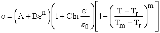 | (1) |
where  is the equivalent low stress,
  is the equivalent plastic strain,
  is the equivalent plastic strain rate,
  is the reference equivalent plastic strain, T is the workpiece temperature,
  is the material melting temperature,
  is the room temperature, and other letters are related to workpiece material from experiment measure.


)


)


)


3. Modeling of Orthogonal Cutting Based on Finite Element
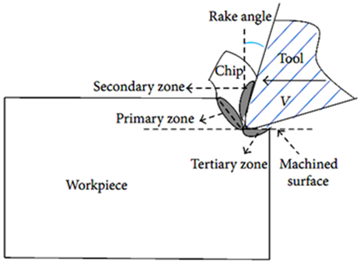
In orthogonal cutting, the material is removed by a cutting edge that is perpendicular to the direction of relative tool-workpiece motion. The orthogonal cutting resembles a shaping process with a straight tool and a metal chip is sheared away from the workpiece. As the edge of tool penetrates into the workpiece, the material ahead of tool is sheared over the primary shear zone to form a chip. The chip partially deforms and moves along the rake face of the tool, which is called the secondary deformation zone.
 Download as
The friction area, where the flank of tool rubs the newly machined surface, is called the tertiary zone [12]. The chip leaves the tool, losing contact with the rake face of the tool, and the length of contact zone depends on the cutting speed, tool geometry, and material properties.
In orthogonal milling, the cutting is assumed to be uniform along the cutting edge; therefore it is a plane strain deformation process without side spreading of the material. Hence, the cutting forces are exerted in the directions of velocity and uncut chip thickness, which are called feed forces and tangential forces [4]. The orthogonal cutting configuration is shown in Figure 1.
4. Methodology of Stress Analysis
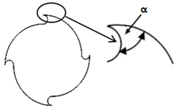
A. Stress at A Cutter Edge
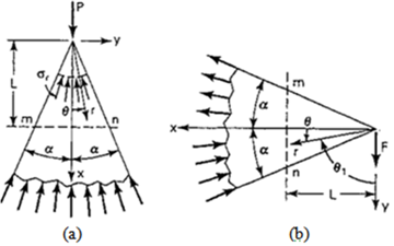
The shape of the cutter edge as described in Figure 2 is assumed as a semi-infinite wedge in Figure 3. The thickness of the wedge is taken as unity, P or F is the load per unit thickness acting at the vertex of a very large or semi-infinte wedge [13, 14].
 Download as
 Download as
Assuming that the stress function for y-direction is
 | (2) |
The corresponding stress components are obtained by the following relations.
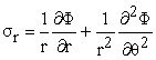 | (3) |
 | (4) |
 | (5) |
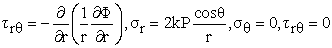
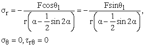
The normal and shearing stresses can be expressed as
 | (6) |
 | (7) |
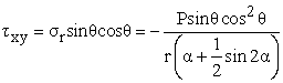 | (8) |
By assuming the stress function for x-direction
 | (9) |
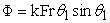
Where θ1 is measured from the line of action of the force. The equilibrium equation is:
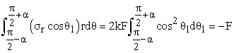 | (10) |
After integration
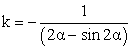 | (11) |
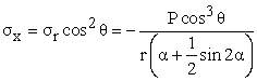
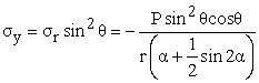
By replacing θ1=90-θ
 | (12) |
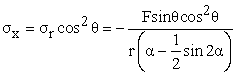 | (13) |
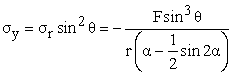 | (14) |
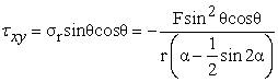 | (15) |
B. Internal Axial Load and Normal Stress due to z Directional Cutting Force
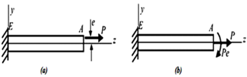
The z directional cutting force acting on the cutter is assumed as an eccentric axial load on the beam. An eccentric axial load is an axial force that does not act through the centroid of the cross section. In Figure (4), where the cantilever beam AE is subjected to a tensile load P acting at distance e from the z axis. The distance e is called the eccentricity of the load.
 Download as
 Download as
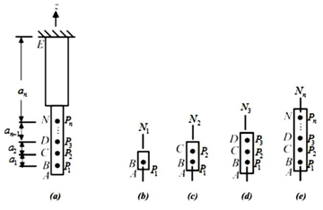
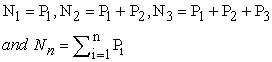
In order to determine the stress due to internal axial force, the beam is divided into segments in Figure (5). N1, N2, N3,…, Nn are the internal axial forces in segments 1,2,3,…,n respectively.
 | (16) |
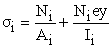
The bending moment M is equal to –Nie, the normal stress at any point in the beam
 | (17) |
Where Ai is the area of the cross section of each segment and Ii is the moment of inertia for each about the y axis.
C. Theories of Failure
For a homogeneous, isotropic material, the characteristic failure stress is either the yield stress or ultimate stress, usually obtained from the uniaxial tensile test. A failure theory relates the stress components to the characteristic value of material failure. The failure of end mills due to yielding or permanent deformation can be investigated using maximum energy of distortion theory [15, 16, 17].
D. Maximum Energy of Distortion Theory (Von Mises)
This theory relates the distortional energy of a point under a general state of stress to that of the tensile specimen at yielding.
The average normal stress
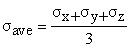 | (18) |
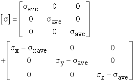
The general state of stress can then be written as
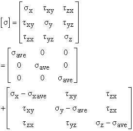 | (19) |
The sum of the normal stress on any three mutually perpendicular surfaces at a point is an invariant. That is
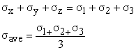 |
The equation can be expressed in terms of the principal stresses as
 |
The distortional energy per unit volume reduces
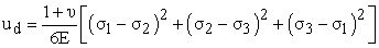 | (20) |
For the tensile test, the state of stress at yielding is  and
and  . Thus at yield, the distortional energy is
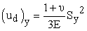 | (21) |
The Von Mises criterion for yielding of an element under a general state of stress due to distortion is
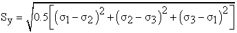 | (22) |
For yield under a single, uniaxial state of stress equivalent to general state of stress is equated  .
.
This equivalent stress is called the Von Mises stress and is given by
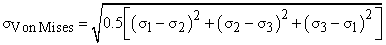 | (23) |
E. Milling Forces Analysis and Validation
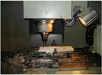
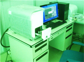
Milling experiments should be carried out to verify the currency of the values got from the finite element simulation. The milling test was conducted in vertical milling machining Vcenter 85W (BT-40), the specifications for Vcenter 85W(BT-40) are X axis travel 850 mm,Y axis travel 600 mm, Z axis travel 560 mm, spindle speed 8000 rpm, spindle motor 5.5 KW, machine dimensions are X length 2450 mm, Y length 2400 mm, Z height 2965 mm, machine weight 5700 kg and cutting tool used in milling test was 19.05 mm diameter end mill equipped with four flutes and a tool holder [12].
 Download as
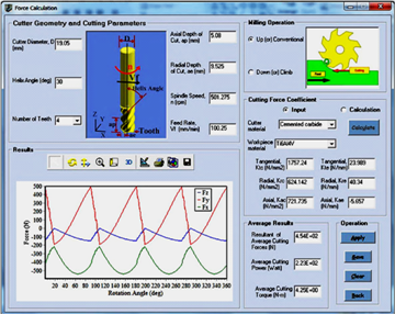
Three-dimensional milling forces are simulated based on chip formation in different cutting parameters. Titanium alloy Ti-6Al-4V is used as workpiece material. The cutting condition is up milling half immersion angle for spindle speed 501.275 rpm, diameter 19.05 mm, feed rate 100.25 mm/min, number of flute 4 flutes, axial depth of cut 5.08 mm, helix angle 30 degree, and cutting forces are shown in Figure 6. It can be noticed that load predictions can be measured in milling process, and then the average values are calculated and obtained based on these data.
 Download as
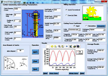
For measuring the cutting forces in, and direction, the Kistler dynamometer is mounted on the machining center. In the up and down milling, cooling method is dry cutting. In order to compare the milling forces between simulation and experiment, the cutting condition and experimental results of cutting forces are shown in Figure 7 and Figure 8.
 Download as
 Download as
It can be noticed that cutting forces are small when the cutting parameter is small; at the same time, cutting efficiency is very low, which is not in the reasonable range and cannot meet the needs of actual production. With the increase of depth of cut and feed, cutting efficiency and the cutting force gradually increase.
 Download as
 Download as
 Download as
F. Methodology for Tool Wear Prediction in Cutting Simulation
The software Deform 2D is used in this study to simulate the two dimensional orthogonal with plane strain deformation metal cutting process. The finite element model is composed of a deformable workpiece and a rigid tool. Overall, there have been a series of cutting test that will be carried out for simulation in varies machining parameters of cutting speed and feed rate.
 Download as
It is postulated in this study that the growth of tool wear can be evaluated at discrete points in time, although in reality it is a continuous process. The proposed procedure for predicting tool wear at any time instance tk can be divided in four phases, as shown in Figure (14). Completion of these four phases makes one simulation cycle that corresponds to one data point on the flank wear (VB) versus cutting time curve at t = tk. Prior to the calculation of wear rates, the quasi-steady state field solutions of the cutting variables (strain, temperature, stress, etc.) are determined in Phase 1 and Phase 2.
 Download as
Local tool wear rates and the worn tool geometry are then calculated in Phase 3, based on the obtained values of cutting variables and the wear rate model used. In Phase 4, the rake face and flank face geometries of the tool in the FEM model are subsequently updated with the results obtained in Phase 3.
When one full simulation cycle is completed, the same procedure is repeated for the next data point, of which the location may be projected based on the local slope of the wear curve at t = tk and a properly selected time increment  . As will be detailed later, this leads to an estimate of the new flank wear width (VBk+1 at t = tk+1) for the updated tool geometry that is used in subsequent simulation. Details for each phase in Figure (14) are described.
G. Tool Wear Cutting Simulation
The proposed procedure was tested using a simple up setting model. The procedure was then applied to the orthogonal cutting process. The preliminary results would indicate the feasibility of this methodology for prediction of the gradual growth of tool wear. The wear rate for each node on the tool constant surface was calculated based on the predicated nodal data of normal stress  , temperature T and sliding velocity
  and Usui’s tool wear model is
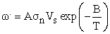 | (24) |
Where the values of the wear constants A and B for workpiece material and uncoated carbide tools.
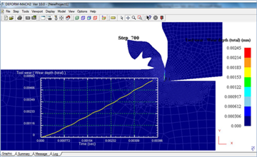
The orthogonal cutting simulation of uncoated carbide tool with an initial sharp edge in cutting Tianium alloy (Ti6Al4V) was carried out based on the proposed procedure. Figure 15 shows the predicted results of total wear depth as highlighted in the oval and the tool rake face geometry.
 Download as
 Download as
 Download as
The simulation showed that higher temperatures lower normal stresses, and lower sliding velocities were observed on the rake face than around the edge radius where significant wear had been expected. It is also important to note that as the Usui’s wear model for titanium alloys considers adhesive wear, it may better describe the flank wear behavior at higher temperatures after a small flank wear land has formed.
 Download as
 Download as
 Download as
5. Conclusion
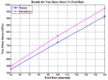
The influence laws of cutting parameters on chips and milling forces are obtained in milling process. The comparison of milling forces in simulation and experiment values is analyzed to verify the feasibility based on finite element method. In evaluation of cutter edge stress, the elasticity theory for semi-infinite wedge was used. The stresses increase with the increase of the feed rate. An increasing the cutting speed and wedge angle can decrease the edge stress. Thus the wedge angle is inversely related to the stresses. Using higher value of depth of cut may occur the shank damage. In general, all stresses in the loaded region are higher than that near fixed end. The edge of cutter can damage easier than the shank.
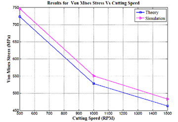
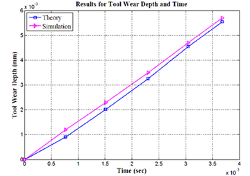
The preliminary results of tool wear simulations using the developed method tend to underestimate the wear rates associated with the crater wear and flank wear, when comparing the tool life with the measured data obtained at the same conditions. The deviation of Von Mises stress between theory and simulation is 4.36% for feed rate 50mm/min, 6.63% for feed rate 100mm/min and 6.33% for feed rate 150mm/min respectively. The deviation of tool wear depth between theory and simulation is 9% for cutting speed 30m/min and feed rate 0.2mm/rev. Moreover, the deviation of Von Mises stress between theory and simulation is 3.33% for 500rpm, 4.35% for 1000rpm and 4.31% for 1500rpm respectively.
The progress of flank wear land verses cutting time for milling Ti-6Al-4V using carbide tools at cutting speed of 30, 60 and 90 m/min, constant feed rate 0.2 mm/rev .The wear occurred rapidly at the initial stage, gradually increased at the second stage and extremely increased at the final stage. The feed rate and cutting speed were found significantly affected the wear depth. Increases the feed rate and cutting speed resulted in increase of the tool wear depth. The highest stress and strain on workpiece occurred in the primary shear zone due to the highest deformation in this region, followed by the secondary shear zone. The maximum generated temperature was found on shearing zone.
Acknowledgment
The author is deeply gratitude to Dr. Myint Thein, Rector, Mandalay Technological University, for his guidance and advice. The author also grateful to Dr. Tin San, Associate Professor and Head, Department of Mechanical Engineering, Mandalay Technological University. The author would like to express grateful thanks to his supervisor Dr. Ei Ei Htwe, Associate Professor, Department of Mechanical Engineering, and to all his teachers from Mandalay Technological University. The author’s special thanks to his parents for constant encouragement during study period.
References
| [1] | Arrazola PJ, Özel T. Investigations on the effects of friction modeling in finite element simulation of machining. International Journal of Mechanical Sciences 2010; 52: 31-42. | ||
 In article In article | View Article | ||
| [2] | Özel T et al. Investigations on the effects of multi-layered coated inserts in machining Ti6Al4V alloy with experiments and finite element simulations. CIRP Annals - Manufacturing Technology 2012; 59:77-82. | ||
| In article | View Article | ||
| [3] | Özel T, Sima M, and Srivastava AK. Finite element simulations of high speed machining Ti6Al4V alloy using modified material models. Transactions of the NAMRI/SME 2010; 38: 49-56. | ||
| In article | |||
| [4] | Umbrello D. Finite element simulaon of conventional and high speed machining of Ti6Al4V alloy. Journal of Materials Processing Technology 2008; 196: 79-87. | ||
| In article | View Article | ||
| [5] | Analysis of Metal Cutting Tool. The University of British Columbia, 1992. | ||
| In article | |||
| [6] | Abdullah Kurt, Modeling of the Cutting Tool Stresses in Machining of Inconel 718 using Artificial Neural Networks. Expert System with Applications. 2009, V36 (6): 9645-9657. | ||
| In article | View Article | ||
| [7] | Wu Qiong, Zhang Yidu, Zhang Hongwei and Zhao Xiaoci. Research on Error Compensation about Deformation of Thin-Wall Part of Aircraft and Milling Cutter [J]. Journal of Wuhan University of Technology. 2008, 9(30):116-120. | ||
| In article | |||
| [8] | Y.-C.Yen, J.S¨ ohner, B. Lilly, and T. Altan, “Estimation of tool wear in orthogonal cutting using the finite element analysis,” Journal of Materials Processing Technology, vol. 146, no.1, pp. 82-91, 2004. | ||
| In article | View Article | ||
| [9] | A. Molinari, X. Soldani, and M. H. Migu´ elez, “Adiabatic shear banding and scaling laws in chip formation with application to cutting of Ti-6Al-4V,” Journal of the Mechanics and Physics of Solids, vol.61, no.11, pp.2331-2359,2013. | ||
| In article | View Article | ||
| [10] | Özel T, Llanos I, Soriano J, and Arrazola PJ. 3D finite modeling of chip formation process for machining Inconel 718: Comparison of FE software predictions. Machining Science and Technology 2011; 15: 21-46. | ||
| In article | View Article | ||
| [11] | Sima M, and Özel T. Modified material constitutive models for serrated chip formation simulations and experimental validation in machining of titanium alloy Ti6Al4V. International Journal of machine Tools & Manufacture 2010; 50: 943-960. | ||
| In article | View Article | ||
| [12] | Y. Altintas, Manufacturing Automation-Metal Cutting Mechanics, Machine Tool Vibrations, and CNC Design, The University of British Columbia, 2000 and 2012.Altintas, C. Brecher, M.Week, and S.Witt, “Virtual machine tool,” CIRP Annals—Manufacturing Technology, vol.54, no.2, pp. 115-138, 2005. | ||
| In article | |||
| [13] | S.P Timoshenko and J.N. Goodier. Theory of Elasticity, 3rd Edition. The McGraw-Hill Companies, Inc. 1970. | ||
| In article | |||
| [14] | Ansel C. Ugural and Saul K.Fenster. Advanced Strength and Applied and Elasticity, 4th Edition. Person Education, Inc. 2003. | ||
| In article | PubMed | ||
| [15] | L.S Srinath, KLingaiah, B Pant and K Ramachandra Experiment Stress Analysis, McGraw-Hill Inc. 1980. | ||
| In article | |||
| [16] | Richard G. Budynas. Advanced Strength and Applied Stress Analysis, 2nd Edition, McGraw-Hill Companies, Inc. 1999. | ||
| In article | |||
| [17] | Madhukar Vable. Mechanics of Materials. 2nd Edition [z] 2009. | ||
| In article | |||
| [18] | T. Kitagawa, K. Maekawa, T. Shirakashi, E. Usui, Analytical prediction of flank wear of carbide tools in turning plain carbon steels. Part 2. Prediction of flank wear, Bull. Jpn. Soc. Precis. Eng. 23 (2) (1989) 126-134. | ||
| In article | |||
 CiteULike
 Delicious


 Knife edge or pivot (b) Wedge cantilever)
Cantilever Beam with an Eccentric Axial Load P, (b) Equivalent Loads P and Pe)
 Beam with axial loads acting at Intermediate points; (b),(c),(d), and (e) Free body diagrams showing the internal axial forces)
 Machine)
)
)