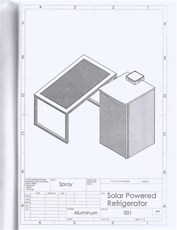
This research is a follow up of the work titled, “Design Analysis of Solar Powered Photovoltaic Refrigerator”. The solar refrigerator was designed to suite Port Harcourt, Nigeria meteorological data. The geographical position of Port Harcourt being at latitude 4040’N and longitude 7010’E. Average solar irradiation of 4.23kWh/m2/day and sunshine hour of 4.25 were prevalent at the position where the Photovoltaic refrigerator would be mounted. The compressor was rated at 0.07kW. The design drawings for the system, the detailed drawings and the assembly drawings were produced with solid works software.
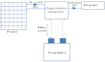
The conventional vapor compression refrigeration system relies on national electrical grid for power to drive the compressor. The photovoltaic refrigerator uses the electrical power supplied the photovoltaic cells 1, 2 having been converted from direct current (DC) to alternating current (AC) to drive the compressor. In all cases, the compressor circulates the working fluid known as refrigerant to extract heat from insulated enclosure known as evaporator. The major components of PV refrigerator are: solar PV panel, charge controller/inverter and refrigerator set. The components of the system are as outlined:
Solar PV Panel
The PV panel cells being semiconductor such as silicon 3, 4 converts sunlight into electrical energy by photovoltaic effect.
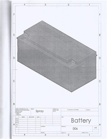
Storage Battery
The direct current from the PV cells are stored as electrical charges in the battery. The stored energy are made available when needed.
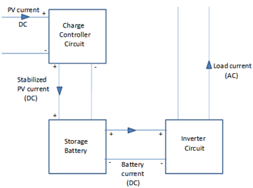
Charge Controller/Inverter Unit
The charge controller regulates the voltage produced from the PV cells before the charges are stored in the battery. It functions also as a medium to prevent the battery from being over-charged or over-discharged. Hence, it supplies the right amount of energy to the battery for prolonged life. The inverter converts the low DC voltage to useable AC voltage. See Figures 1 and 2.
Other vital components required to build the PV refrigerator are as follows:
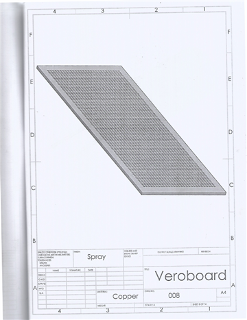
Vero Boards
This is a preformed circuit board made from copper strips and mounted on insulating bonded paper. It forms a more permanent circuit with more reliable connections than the one built from breadboard.
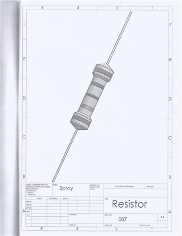
Resistors
This regulates the flow of electrical current in the circuits.
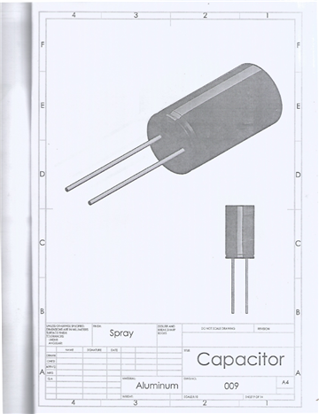
Capacitors
Capacitors are means of storing electrical energy in a circuit. They serve to stabilize energy flow of the system as well as band filters for passage of specific amount of current and voltage of specified waveform and frequency.
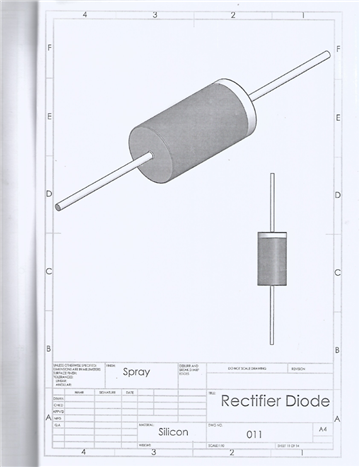
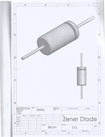
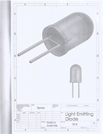
Diodes
Diodes are used as signal rectifier, signal limiters, voltage regulators, switches, signal modulators, signal mixer, signal demodulators and oscillators.
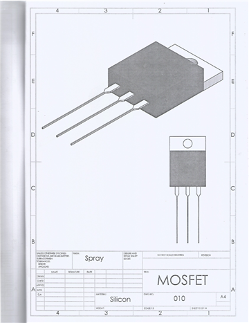
Transistors
Transistors regulate voltage or current flow in electrical circuits and act as button or gate for electronic system.
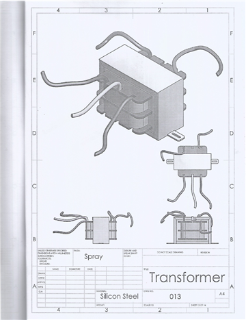
Transformer
This acts in any circuit as voltage or current regulator. It could be a step-up or step-down transformer.
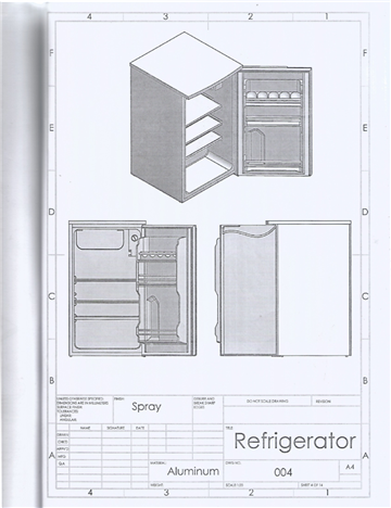
A. Sizing the Refrigerator
The refrigerator whose specification is displayed in Table 1 was selected. The required to drive the compressor of this model of refrigerator is relatively low compared with other refrigerators of the same size.
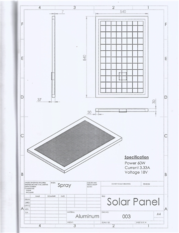
B. Sizing of the PV Solar Module/Panel
In a solar PV panel, each cell produces half a volt no matter the size but the amount of current generated is dependent on the size of the cell. Larger cells produce higher amperage while smaller cells produce lesser. A panel is made up of 30 to 36 cells to comfortably charge a 12 volts battery. Extra cost of panels with more than 36 cells is not justified for charging 12 volts battery. In the process, the panel with specification in Table 2 was selected.
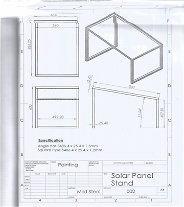
C. PV Panel Stand
The PV panels collect solar radiation directly from the sky, ground irradiation and surrounding area of the PV panel. Orientation of the solar panel is a critical parameter in optimizing and maximizing its exposure to direct sunlight thereby improving upon the collection efficiency. Solar isolation angle varies throughout the year. Hence, the panel optimal tilt angle in winter will differ from that in summer. The angle is also affected by the latitude of any given place on the earth surface. In Port Harcourt environment, for optimal summer performance, the tilt angle should be 150 less than the latitude of the place. The recommended tilt angle for the panel for optimal summer and winter performance is 110. To mitigate against heat generation, the PV panel is placed in area where there is adequate ventilation. Mild steel is preferred to aluminium as construction material. The fact being that mild steel is cheaper, tough and more resilient; though aluminium is malleable and ductile.
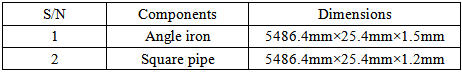
Angle iron and square pipes are employed in the construction of PV panel stand. The material specification is displayed in Table 3
D. Sizing of Charge Controller
The charge controller is rated to withstand the maximum current produced by the PV panel as well as the maximum load current. A safety factor is considered to ensure that the charge controller handles the maximum current produced by the PV panel in excess of the designed value. On a very sunny day the PV panel could produce excess 25% current above the rated or designed current output. Charge controller sizing takes into consideration the short circuit current, the factor of safety and the actual number of PV modules connected in parallel.
The current requirement of the charge controller (ICC) is expressed as:
 | (1) |
where,
 --Actual number of PV module in parallel.
 -short circuit current of the module.
E. Sizing the Inverter
The inverter converts the direct current (DC) produced by the solar panel stored in the battery as direct current to alternating current (AC). The alternating current is required to power the compressor of the refrigerator. It is required of the inverter to adequately be able to handle the power demand of the compressor.
The power requirement of the inverter (WINV) in order to efficiently drive the compressor of the refrigerator is as expressed:
 | (2) |
where,
 --power rating of the compressor.
F. Sizing of the Transformer
The transformer is sized to meet the voltage demand of the compressor of the refrigerator. A center tap step-down transformer was chosen, with a rating of 230 volts at the primary side and 12 V-0-12 V/5 A at the secondary side.
G. Fabrication Procedure for the PV Panel Stand
Metal cutting and welding are mainly the fabrication procedures for the PV panel stand. The basic steps involved are as outlined:
With measuring tape and permanent marker, mark out 400 mm twice on one square inch pipe.
With the use of hacksaw cut the marked spots to obtain two 400 mm long one-inch square pipe.
Again with measuring tape and permanent marker mark out twice 200 mm length on one square inch pipe. The take cuts to produce two 200 mm long of this pipe.
Repeat the same procedure to obtain two 519 mm long square inch pipes.
With measuring tape and permanent marker, mark out 840 mm twice on angle iron. With hacksaw take cuts to produce two pieces.
Repeat the same procedure to produce two 540 mm lengths of angle iron.
Position the four pieces of angle iron and weld carefully to get the right joint strength.
Position the two 400 mm square pipes and the two 200 mm square inch pipes and weld accordingly.
Finally place the two 519 mm long square inch pipe and weld carefully and dress all the joints to the required level of finishing.
H. Fabrication Procedure for Charge Controller/Inverter Units
The charge controller/inverter units (CCIU) consist of charge controller circuit, inverter circuit and the storage battery.
(i). Charge Controller Circuit (CCC)
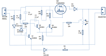
The building block consists of vero board, one light emitting diode (LED), two rectifier diode, one zener diode, two 0.1µF capacitors, three 10kΩ resistors, two 20kΩ resistors, one 18 kΩ resistor, one 4. 7kΩ resistor, one 3.9kΩ resistor, one 1kΩ resistor, 0ne 10kΩ variable resistor, three bipolar junction transistors (BJT), one-insulated-gate bipolar transistor (IGBT) and a 12V battery. The circuit diagram after soldering on a continuous connection vero board interface is as shown in Figure 3.
The following steps are followed in fabrication of charge controller circuits.
(a) The positive and negative terminals of the PV panel were connected to the two continuous lines of the vero board.
(b) Resistor R1 was connected to the cathode of D1 which is a red led to indicate current flow to the vero board.
(c) Resistors R1, R2, zener diode D2 and transistor Q1 serve as voltage regulator in the circuit.
(d) The IGBT (FQP27PO6) serves as the main current amplifier in the circuit.
(e) Diodes D1 and D2 are employed to ensure that current flow in the circuit is only in one direction. This is to prevent current flow from the battery towards the PV panel.
(ii) Inverter Circuit
The components used in building the inverter circuit include a vero board, two metal oxide semiconductor field transistor (MOSFET),four 330Ω resistors, a center tapped transformer (with a rating of 230V primary and 12-0-12V/5A secondary. These components are soldered on continuous connection vero board interface. The circuit diagram is as presented in Figure 4.
The following procedures are involved in the construction of the inverter:
(a) The pins of the MOSFET using IRFZ44datasheet.
(b) The gate of MOSFET one was connected to the drain of MOSFET two via a 330Ω resistor.
(c) The gate of MOSFET two was connected to the drain of MOSFET one via a 330Ω resistor.
(d) Two 330 resistors were connected in series to the source of both MOSFETs.
(e) Resistors R5 and R6 were connected in series and the nose tapped and connected to the negative terminal of the battery.
(f) The drain pin of MOSFET one was connected to one of the 12V Outlet of the transformer secondary and the drain pin of MOSFET two connected to the other 12V outlet of the transformer.
(g) The center tap of the transformer was connected the battery’s positive terminal.
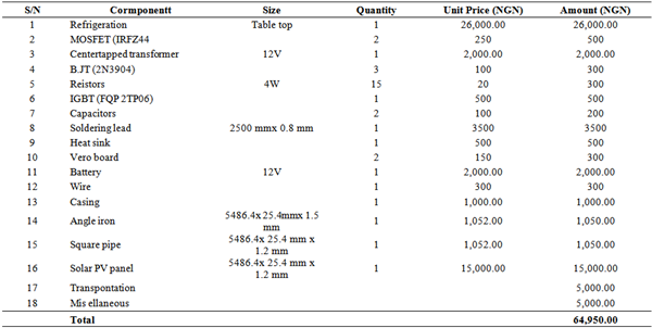
The costs of the various components used in the construction of the solar powered photovoltaic refrigerator is as shown in Table 4.
The different modules and their component parts required for the fabrication of solar powered photovoltaic refrigerator had been presented. The detailed and assembly drawings were produced with solid works software. The fabrication procedure entails processes such as metal cutting, welding, wiring, soldering and coupling of individual modules. From the performance point of view, the solar powered PV refrigerator is as efficient as the one powered from the national grid and more so noiseless and not prone to environmental pollution. On the of input power requirement to drive the compressor, the solar powered refrigerator requires 60 watts while the one powered from the national electric grid is 70 watts. In a nutshell, the solar powered refrigerator design for Port Harcourt environment in Rivers State Nigeria is the best campaign in terms of performance evaluation and power rating. The detailed drawings and assembly drawing is as presented in Appendix I.
|
|
|
|
|
|
|
|
|
|
|
|
|
| [1] | Alamsyah et al (2003). Techno-economic Analysis of a Photovoltaic System to Provide Electricity for a Household in Malaysia. Proceedings in International Symposium on Renewable Energy: Environmenr Protection and Energy Solution for sustainable Development , Kuola Lunpur, pp. 387-396. | ||
| In article | |||
| [2] | Assad, A (2006). A Stand Alone Photovoltaic System, Case Study: A Residence in Gaza. Journal of Applied Sciences in Environmental Sanitation. Vol. 5, no. 1, pp. 81-91. | ||
| In article | |||
| [3] | Mahmood et al (2006). Techno-economic Feasibility of Energy Supply to Remote Village in Palestine by PV-System. Diesel generator and Electric Grid Renewable Sustainable Energy Rev., vol. 10, pp. 128-138. | ||
| In article | View Article | ||
| [4] | Photoelectric emission (2013). http//www.physics-and-radio-electronic.com/ electronic -devices-and-circuits/electron-emmission/photoelecricemmission.html [accessed 29/06/18]. | ||
| In article | |||
Published with license by Science and Education Publishing, Copyright © 2023 Dr. Mathew Shadrack Uzoma, Dr. M. M. Ojapah and Engr Eseonu Obi
![]() This work is licensed under a Creative Commons Attribution 4.0 International License. To view a copy of this license, visit
http://creativecommons.org/licenses/by/4.0/
This work is licensed under a Creative Commons Attribution 4.0 International License. To view a copy of this license, visit
http://creativecommons.org/licenses/by/4.0/
| [1] | Alamsyah et al (2003). Techno-economic Analysis of a Photovoltaic System to Provide Electricity for a Household in Malaysia. Proceedings in International Symposium on Renewable Energy: Environmenr Protection and Energy Solution for sustainable Development , Kuola Lunpur, pp. 387-396. | ||
| In article | |||
| [2] | Assad, A (2006). A Stand Alone Photovoltaic System, Case Study: A Residence in Gaza. Journal of Applied Sciences in Environmental Sanitation. Vol. 5, no. 1, pp. 81-91. | ||
| In article | |||
| [3] | Mahmood et al (2006). Techno-economic Feasibility of Energy Supply to Remote Village in Palestine by PV-System. Diesel generator and Electric Grid Renewable Sustainable Energy Rev., vol. 10, pp. 128-138. | ||
| In article | View Article | ||
| [4] | Photoelectric emission (2013). http//www.physics-and-radio-electronic.com/ electronic -devices-and-circuits/electron-emmission/photoelecricemmission.html [accessed 29/06/18]. | ||
| In article | |||


