The performance of fin is of major concern for heat transfer applications. The present study dealt with experimental investigations of the thermal performance for perforated pin fin arrays. The fins are perforated with circular and hexagonal fins along flow direction. Forced convection heat transfer at Reynold number range between 1-3.5 x 10⁴ have been investigated. The perforated pin fin arrays were tested against a base case of solid pin fin array of the same fin dimension. The pin fin arrays with hexagonal perforations exhibited the best performance with enhanced convective heat transfer coefficient, fin effectiveness, and fin efficiency. Thermal resistance decreased in hexagonal perforation than circular perforation and solid fins.
Extended surfaces (fins) are used in a large number of applications to enhance the heat transfer to and from surfaces. The shape of the fins, along with the geometric characteristics affect the thermal performances. Plate and pin fins are widely used in practice owing to their simple machining requirement 1.
Copper and aluminum alloy pin fins are mostly used in engineering applications owing to their thermal characteristics. Aluminium alloys are preferred in aerospace applications owing to their lightweight nature. These fins are also found in automotive and railway applications 2.
Solid and phase changing material filled pin fins have been introduced to effectively cool electronic applications 3. Recently, they have increasing application in gas turbines component cooling 4.
The shape factor of the pin fin arrays plays a significant role in the thermal performance. Ehteshum et al 5 investigated on the heat transfer characteristics of both solid and circular perforated rectangular fin array under turbulent inflow. Sahin et al. 6 investigated on the heat transfer characteristics and pressure drop over a square perforated pin fin array in a rectangular channel and found that the use of the square perforations in pin fin arrays lead to enhanced heat transfer. The enhancement efficiencies obtained for these fins were between between 1.1 and 1.9 depending on the clearance ratio and inter-fin spacing ratio. Buiyan et al. 7, 8, 9 investigated on the thermal and hydraulic performances of pin fin and wavy fin textures for transitional and turbulent inflow regime. The studies suggested that the heat transfer is enhanced with the decrease in the longitudinal and transverse pitch and the increase in fin pitch. Similar trend in pressure drop characteristics are registered by Buiyan et al. 7, 8, 9. Tanda 10 studied heat transfer and pressure drop performance on a rectangular channel equipped diamond-shaped fin arrays. Thermal performance comparisons with suggested that heat transfer is increased by a factor of up to 4.4 for equal and by a factor of up to 1.65 for equal pumping power for diamond shaped arrays when compared to the plain rectangular arrays.

This work focuses on the physics of heat transfer process pertaining to forced convection across perforated fin array. Fin arrays of circular cross sectioned pin types were tested with circular and hexagonal perforations. The base pin was heated with constant flux. The velocity of the inflow was varied between 4 ms-1 to 12 ms-1.
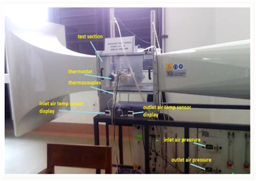
Figure 2 depicts the experimental setup. The fin configurations mounted in thermostat-controlled heating box were installed inside the low-subsonic wind tunnel. Both inlet and outlet air pressures along with the flow velocity were taken from the data acquisition system of the wind tunnel. Measurements of inlet and outlet air temperatures were also carried out. Fin surface temperatures were carried out using thermostat.
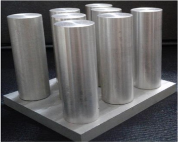
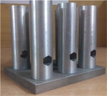
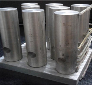
In Figures 3.a-3.c, solid, circular and hexagonal shape perforated pin fin arrays are shown. The fin arrays were machined from solid aluminium blocks. using CNC machine.
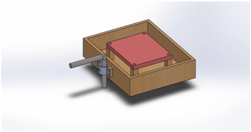
Figure 4 depicts the heater box used for the different fin configurations. The dimensions of the box were taken as 201 mm x 170 mm x 47 mm. The box was insulated with glass wool and asbestos. Two aluminum pins of dimensions 120 mm x 100 mm were bolted together which held a heating coil of 440 W in between. Provisions was made to attach the heater box with the three-component balance of the wind tunnel.
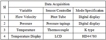
The following sensors/data acquisition modules were used to measure the system variables:
 |
The working fluid for the experiments was taken as air. The average effective velocity of the flow impinged on the fin structures was calculated as 4
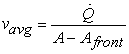 | (1) |
Flow Reynolds number was calculated from the average inflow velocity as
 | (2) |
The system Nusselt number for the fin arrays was calculated as
 | (3) |
Hence, the convective heat transfer coefficient for the fin array had been calculated as:
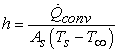 | (4) |
The bulk temperature of the fluid within the system:
 | (5) |
The thermal resistance is calculated as:
 | (6) |
Fin efficiency,  is defined as the ratio of actual heat transfer rate from the fin to the ideal heat transfer rate from the fin if the entire fin were at base temperature.
 | (7) |
Fin effectiveness,  is the ratio of heat transfer from fin to heat transfer from fin base without fin
 | (8) |
The static pressure drop  across the fin arrays is calculated from the wind tunnel data acquisition system. The dimensionless pressure drop
  is calculated as
 | (9) |
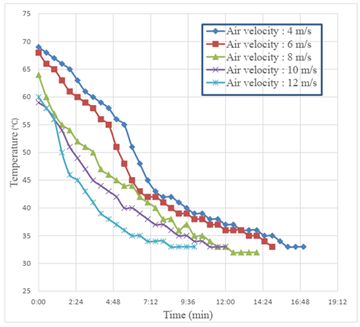
Figure 5 depicts the cooling rate of pin fins at 4 ms-1 inflow. The solid pin fin takes almost 17 minutes, pin fin with circular perforation needs almost 14 minutes and pin fin with hexagonal perforation needs 7 minutes for cooling down to the room temperature.

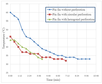
The cooling rate of different pin fins at 6 ms-1 are presented in Figure 6. The solid pin fin without any perforation takes almost 15 minutes for reaching the room temperature; pin fin with circular perforation needs almost 12 minutes, pin fin with hexagonal perforation needs 6 minutes.

Figure 7 presents the cooling rate of different pin fin configurations at 8 ms-1 inflow. From the graph, we find that the solid pin fin without any perforation takes almost 14 minutes for reaching the room temperature; pin fin with circular perforation needs almost 11 minutes and pin fin with hexagonal perforation needs 5 minutes.

The cooling rate of different pin fins at 10 ms-1 are presented in Figure 8. The solid pin fin without any perforation takes almost 12 minutes for reaching the room temperature; pin fin with circular perforation needs almost 8 minutes, pin fin with hexagonal perforation needs 3 minutes.
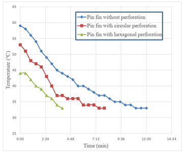
Figure 9 presents the cooling rate of different pin fin configurations at 12 ms-1 inflow. The solid pin fin without any perforation takes almost 10 minutes for reaching the room temperature; pin fin with circular perforation needs almost 7 minutes, pin fin with hexagonal perforation needs 4 minutes.
The results presented in Figure 5 – Figure 9 attest that the pin fin arrays with hexagonal perforations are the most effective variant. This is owing to the increased heat transfer area for the hexagonal perforations. The pin fin arrays with circular perforations are the second most effective variant. Both perforated fin array types show improved performance when compared to the solid pin fin arrays. As expected, the increase in flow rate results in a higher convective heat transfer for all variant, which is evident in the accelerated cooling of the different pin fin arrays.
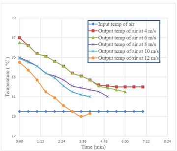
Figure 10 depicts the heating rate of the air past the solid pin fins. The input temperature remains nearly constant throughout the cooling time for all the air velocity. The time required for the temperature of output to become close to the input ambient temperature for 4 ms-1, 6 ms-1, 8 ms-1, 10 ms-1, and 12 ms-1 was 17 minutes, 15 minutes, 14 minutes, 12 minutes, and 10 minutes respectively.
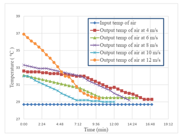
Figure 11 depicts the heating rate of the air past the pin fins with circular perforations. The time required for the temperature of output to become close to the input ambient temperature for 4 ms-1, 6 ms-1, 8 ms-1, 10 ms-1, and 12 ms-1 was 14 minutes, 12 minutes, 11 minutes, 8 minutes, and 7 minutes respectively.
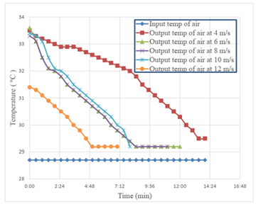
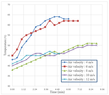
Figure 12 depicts the heating rate of the air past the pin fins with hexagonal perforations. The time required for the temperature of output to become close to the input ambient temperature for the different inflow velocities of 4 ms-1, 6 ms-1, 8 ms-1, 10 ms-1, and 12 ms-1 was 7 minutes, 6 minutes, 5 minutes, 4 minutes, and 4 minutes respectively. Hence for the 12 ms-1 inflow, the cooling rate of the perforated pin fin arrays is rapid. As the temperature measurement was done on single points at in and outlet positions, the fact that the outlet temperature is registered less than the inlet temperature is possible for this case, as the higher flowrate might induce secondary flow patterns at the wake of the perforated fin arrays.
The results shown in Figure 10 - Figure 12 show that the pin fins with hexagonal perforations have the highest heat transfer rate, followed by the circular perforated fins. For pin fins with hexagonal perforations, the flow rates with 4 ms-1 and 6 ms-1 velocity resulted in the highest temperature difference between incoming and outgoing air temperatures. For higher flow rates, the differences between in and outgoing air temperatures are minimal. For solid and circular perforated pin fins, the 4 ms-1 inflow cases showed residual temperature difference between in- and outlet air.


The heating time required for the different pin fin configurations under varying flow rates are depicted in Figure 13 (a, b, c). The results for solid pin fins are presented in Figure 13 (a), and for pin fins with circular and hexagonal perforations are presented in Figure 13 (b), and Figure 13 (c) respectively. The solid pin fins reached the highest temperature, followed by the circular and hexagonal perforated pin fins. For hexagonal perforated pin fins, equilibrium temperature were not achieved for the higher flow rates.
The cooling time of the different pin fin array configurations are presented in Figure 14 (a, b, c). Hence, the results for solid pin fin arrays are presented in Figure 14 (a), and those for the pin fins with circular and hexagonal perforations are presented in Figure 14 (b) and Figure 14 (c) respectively. For increasing flow rate of air, the forced convective heat transfer increases, thus decreasing the time to achieve equilibrium temperature at the base pin of the different fin arrays. Hence, the pin fins with hexagonal perforations require less than half of the cooling time when compared to the variations with circular perforations, and solid pin fin arrays.


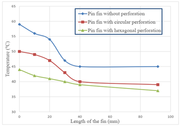

The temperature distributions along the fin surfaces of different pin fin configurations under varying flowrates are presented in Figure 15 (a, b, c, d, e). A general trend of decreasing surface temperature along the length of the fins is observed for all cases. The temperature difference is substantial for the lower half portion of the fins. The hexagonal perforated variant exhibited the highest temperature difference for all flowrates except for the 12 ms-1 inflow case, where the circular perforated fin array experienced the highest surface temperature difference.
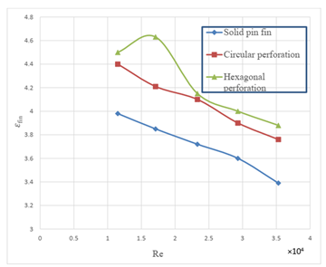
The effect of Reynolds number on fin effectiveness for different kinds of pin fins is shown in Figure 16. The result suggests that fin effectiveness for pin fin with hexagonal perforation is the highest followed by that with circular perforation. Both perforated pin fins exhibited higher fin effectiveness than the solid pin fin. The highest fin effectiveness values for the perforated variants are found within the Reynolds number range of 1-2 x 10⁴. All variants show a detrimental fin effectiveness for increasing Reynolds number.
The effect of Reynolds number on fin efficiency for different kinds of pin fins is shown in Figure 17. The result show that fin efficiency for pin fin with hexagonal perforation is comparatively higher when compared to the other variants. The fin efficiency decreases with increasing Reynolds number which is due to the fact that, the base temperature decreases with higher flow rate, as observed in Figure 13 (a, b, c).

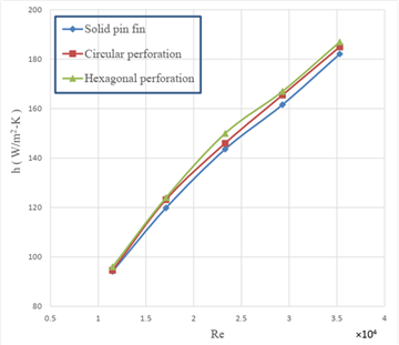
The effect of Reynolds number on convective heat transfer coefficient is shown in Figure 18. The result suggests that the hexagonal perforated pin fin exhibits higher convective heat transfer coefficient than the other pin fin arrays. Also, the results show an increase in the convective heat transfer coefficient with increasing Reynolds number.
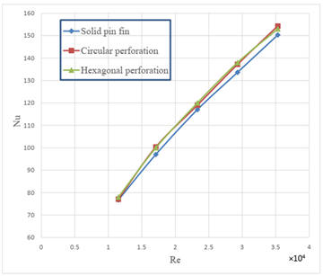
The effect of varying Reynolds number on the pin fin Nusselt numbers is shown in Figure 19. The Nusselt number for pin fin with hexagonal perforation is found to be comparatively higher, followed by that with circular perforation and of solid pin fins. The Nusselt number is increased with the increasing Reynolds number for all variants of pin fin arrays.
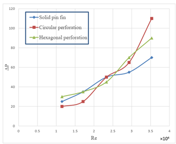
The effect of Reynolds on pressure drop is shown in Figure 20. In general, the pressure drop is increased with the increasing Reynolds number and also with the perforation due to increased pressure loss factor. Hence, the pressure drop of circular perforated pin fins increase drastically at the higher Reynolds number regime, with the hexagonal perforated pin fins and the solid pin fins following the trend. At lower Reynolds number, where the pin efficiency is significant, the circular perforated pin fin exhibited the lowest pressure drop.
The effect of Reynolds number on dimensionless pressure drop is shown in Figure 21. The result suggests that dimensionless pressure drop for pin fin with hexagonal perforation is comparatively higher than the solid pin fins at low Reynolds number range. The dimensionless pressure drop is decreased with the increasing Reynolds number. At higher Reynolds number, the value of  is higher for the pin fins with circular perforations when compared to the value of the hexagonal perforated pin fins and solid pin fins.

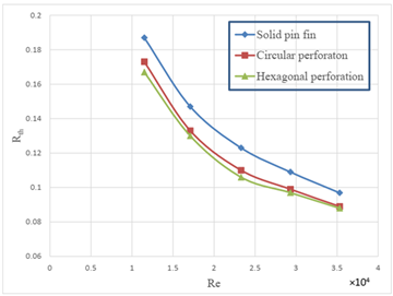
The effect of Reynolds number on thermal resistance is shown in Figure 22. The graphs suggest that the thermal resistance for pin fin with hexagonal perforation is slightly less than that with the circular perforated pin fins for the range of Reynolds number relevant for this study. Both variants, however, are characterized to have lower thermal resistance than the solid pin fin. The thermal resistance is decreased with the increasing Reynolds number.
In this work two different perforations are tested on pin fin along with solid pin fin variant to observe different heat transfer parameters with varied Reynolds Number. The values of Nusselt number, convective heat transfer coefficient and pressure drop increase with increasing Reynolds number for all pin fins. Perforated fins show higher values of  and
and  than solid fins. Between circular and hexagonal perforation, the hexagonal perforation observe higher value of
  and
and  . The values of thermal resistance, efficiency, effectiveness and dimensionless pressure drop, in general, decrease with the increasing Reynolds number for all the fins.
This paper documents the experimental investigation of the thermal characteristics of different pin fin arrays. Bulk characteristic flow numbers are calculated using the flow variables. The inclusion of perforation enhances the effectiveness of the pin fin system (Figure 16). It is experienced that the effect of increased Reynolds number increases the convective heat transfer rate (Figure 18). The efficiency of the system decreases with increasing Reynolds number (Figure 17). Overall, the pin fin with hexagonal perforations performed the best, followed by the pin fin with circular perforation. The optimum Reynolds number for heat transfer is found to be 1.75 x 10⁴. At higher Reynolds number concerning this experiment, the pin fin with circular perforation exhibited substantial increase in dimensionless pressure drop.
 |
| [1] | D.E. Metzger, C.S. Fan, S.W. Haley, Effects of pin shape and array orientation on heat transfer and pressure loss in pin fin arrays, J. Eng. Gas Turbines Power 106 (1984) 252-257. | ||
| In article | View Article | ||
| [2] | Yunus A. Çengel, 2004, “Heat Transfer- A Practical Approach”, SI units 3rd Edition, Tata McGraw Hill Co., Pg. No.: 159. | ||
| In article | |||
| [3] | Ali, H. M., Arshad, A., Jabbal, M., & Verdin, P. G.. “Thermal management of electronics devices with PCMs filled pin-fin heat sinks: a comparison” International Journal of Heat and Mass Transfer, 117, 1199-1204. 2018. | ||
| In article | View Article | ||
| [4] | Fernandes Royce, “Investigation of Pin Fin Cooling Channels for Applications in Gas Turbines”, PhD Thesis, 2016. | ||
| In article | |||
| [5] | Mehedi Ehteshum*, Mohammad Ali, Md. Quamrul Islam, Muhsia Tabassum, Thermal and hydraulic performance analysis of rectangular fin arrays with perforation size and number, 6th BSME International Conference on Thermal Engineering (ICTE 2014). | ||
| In article | View Article | ||
| [6] | Bayram Sahin, Alparslan Demir, “Performance analysis of a heat exchanger having perforated square fins”, ELSEVIER, Applied Thermal Engineering 28 (2008) 621-632. | ||
| In article | View Article | ||
| [7] | A. A. Bhuiyan, A. K. M. Sadrul Islam, M. R. Amin, “Numerical study of 3D thermal and hydraulic characteristics of wavy fin-and-tube heat exchanger”, Frontiers in heat and mass Transfer (FHMT) 3 - 033006, 2012. | ||
| In article | View Article | ||
| [8] | A. A. Bhuiyan, M. R. Amin, A. K. M. Sadrul Islam, “Three-Dimensional Performance Analysis of Plain Fin Tube Heat Exchangers in Transitional Regime”, Applied Thermal Engineering, Vol 50, Issue 1, pp 445-454, 2013. | ||
| In article | View Article | ||
| [9] | A. A. Bhuiyan, M. R. Amin, R. Karim, A. K. M. Sadrul Islam, “Plate fin and tube heat exchanger modeling: Effects of performance parameters for turbulent flow regime”, International Journal of Automotive and Mechanical Engineering (IJAME), 9(1), pp. 1768-1781, 2014. | ||
| In article | View Article | ||
| [10] | Giovanni Tanda, “Heat transfer and pressure drop in a rectangular channel with diamond-shaped elements”. In International Journal of Heat and Mass Transfer Volume 44, Issue 18, September 2001, Pages 3529-3541. | ||
| In article | View Article | ||
Published with license by Science and Education Publishing, Copyright © 2023 Md Lutfor Rahman and Irfan Ahmed
![]() This work is licensed under a Creative Commons Attribution 4.0 International License. To view a copy of this license, visit
http://creativecommons.org/licenses/by/4.0/
This work is licensed under a Creative Commons Attribution 4.0 International License. To view a copy of this license, visit
http://creativecommons.org/licenses/by/4.0/
| [1] | D.E. Metzger, C.S. Fan, S.W. Haley, Effects of pin shape and array orientation on heat transfer and pressure loss in pin fin arrays, J. Eng. Gas Turbines Power 106 (1984) 252-257. | ||
| In article | View Article | ||
| [2] | Yunus A. Çengel, 2004, “Heat Transfer- A Practical Approach”, SI units 3rd Edition, Tata McGraw Hill Co., Pg. No.: 159. | ||
| In article | |||
| [3] | Ali, H. M., Arshad, A., Jabbal, M., & Verdin, P. G.. “Thermal management of electronics devices with PCMs filled pin-fin heat sinks: a comparison” International Journal of Heat and Mass Transfer, 117, 1199-1204. 2018. | ||
| In article | View Article | ||
| [4] | Fernandes Royce, “Investigation of Pin Fin Cooling Channels for Applications in Gas Turbines”, PhD Thesis, 2016. | ||
| In article | |||
| [5] | Mehedi Ehteshum*, Mohammad Ali, Md. Quamrul Islam, Muhsia Tabassum, Thermal and hydraulic performance analysis of rectangular fin arrays with perforation size and number, 6th BSME International Conference on Thermal Engineering (ICTE 2014). | ||
| In article | View Article | ||
| [6] | Bayram Sahin, Alparslan Demir, “Performance analysis of a heat exchanger having perforated square fins”, ELSEVIER, Applied Thermal Engineering 28 (2008) 621-632. | ||
| In article | View Article | ||
| [7] | A. A. Bhuiyan, A. K. M. Sadrul Islam, M. R. Amin, “Numerical study of 3D thermal and hydraulic characteristics of wavy fin-and-tube heat exchanger”, Frontiers in heat and mass Transfer (FHMT) 3 - 033006, 2012. | ||
| In article | View Article | ||
| [8] | A. A. Bhuiyan, M. R. Amin, A. K. M. Sadrul Islam, “Three-Dimensional Performance Analysis of Plain Fin Tube Heat Exchangers in Transitional Regime”, Applied Thermal Engineering, Vol 50, Issue 1, pp 445-454, 2013. | ||
| In article | View Article | ||
| [9] | A. A. Bhuiyan, M. R. Amin, R. Karim, A. K. M. Sadrul Islam, “Plate fin and tube heat exchanger modeling: Effects of performance parameters for turbulent flow regime”, International Journal of Automotive and Mechanical Engineering (IJAME), 9(1), pp. 1768-1781, 2014. | ||
| In article | View Article | ||
| [10] | Giovanni Tanda, “Heat transfer and pressure drop in a rectangular channel with diamond-shaped elements”. In International Journal of Heat and Mass Transfer Volume 44, Issue 18, September 2001, Pages 3529-3541. | ||
| In article | View Article | ||


