Heat transfer enhancement has been a major concern in modern days in designing heat generating equipment. In the present study experimental investigations has been carried out to analyze the thermal performance of plate fin arrays for solid, circular and hexagonal perforations along the length of the fin in different Reynolds number flow under steady state forced convection. The flow velocity was varied ranging from 4 ms-1 to 12 ms-1 and the experimental data were recorded after a certain period of time at a constant heat flux. The performance of plate fin as heat sink was tested and best result was found in case of plate fin with hexagonal perforation heat sink. Convective heat transfer coefficient, fin effectiveness, and fin efficiency were tested to have increased in hexagonal perforation for plate fin arrays. Thermal resistance seems to decrease in hexagonal perforation than circular perforation and solid fins. This study suggests that most important parameter that governs the performance of fin is the fin geometry and varied cross section i.e., perforations.
Extended surface (fin) is used in a large number of applications to increase the heat transfer from surfaces. Typically, the fin material has a high thermal conductivity. The fin is exposed to a flowing fluid, which cools or heat sit, with the high thermal conductivity allowing increased heat being conducted from the wall through the fin. Fins are used to enhance convective heat transfer in a wide range of engineering applications and offer practical means for achieving a large total heat transfer surface area without the use of an excessive amount of primary surface area. Two most common types of fins widely used are plate fins and pin fins 1. The plate fins have a rectangular cross section and the pin fins have circular cross section. These fins are connected to a base plate which is to be cooled. Aluminum alloy plate fins along with heat sinks have been used in the aircraft industry for more than 60 years and adopted into the cryogenic air separation industry around the time of the second world war and shortly afterwards into cryogenic processes in chemical plants such as Natural Gas Processing. They are also used in railway engines and motor cars 2. Pin fins and pin fin heat sinks are used in many devices nowadays and works excellently with LEDs compared to other techniques 3. Ehteshum et al 4 investigated on the turbulent heat transfer performance of rectangular fin array with both solid and circular perforated textures. Sahin et al. 5 investigated on the heat transfer enhancement and the corresponding pressure drop over a flat surface equipped with square cross-sectional perforated pin fins in a rectangular channel. The experimental results showed that the use of the square pin fins may lead to heat transfer enhancement. Enhancement efficiencies varied between 1.1 and 1.9 depending on the clearance ratio and inter-fin spacing ratio. Buiyan et al. 6, Buiyan et al. 7, and Buiyan et al. 8, studied thermal and hydraulic performance of plate fin, wavy fin and tube heat exchanger for transitional and turbulent flow regime. The studies registered that the heat transfers and pressure drop performance increase with the decrease in the longitudinal, transverse pitch and the increase in fin pitch. Tanda 9 studied heat transfer and pressure drop experiments on a rectangular channel equipped with arrays of diamond-shaped elements. Thermal performance comparisons with data showed that the presence of the diamond-shaped elements enhanced heat transfer by a factor of up to 4.4 for equal and by a factor of up to 1.65 for equal pumping power for diamond shaped arrays when compared to the plain rectangular arrays.

This work focuses on the physics of heat transfer process pertaining to forced convection across perforated fin array. Fin arrays of plate types were tested with circular and hexagonal perforations. The base plate was heated with constant flux. Forced convection was ensured with the velocity of the fluid varied between the values of 4 ms-1 to 12 ms-1. The effects of perforations were compared with reference solid plate type fin arrays.
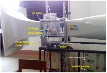
Figure 2 depicts the experimental setup. The fin configurations mounted on thermostat-controlled heating box were mounted inside the low-subsonic wind tunnel. Both inlet and outlet air pressures along with the flow velocity were taken from the data acquisition system of the wind tunnel. Measurements of inlet and outlet air temperatures were also carried out. Fin surface temperatures were carried out using thermostat.
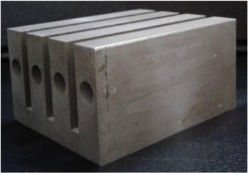
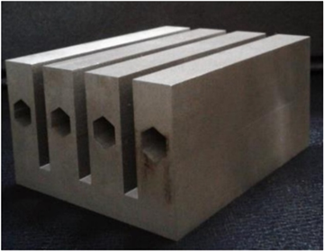
In figures 3.a-3.c, the variants of plate fin arrays used in this study. The fin arrays were machined from solid aluminium blocks. For the baseline case, solid rectangular fins were used. In two further variations, circular and hexagonal perforations were made using CNC machine.

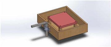
The design of the heater box used for the different fin configurations is shown in Figure 4. The dimensions of the box were 201 mm x 170 mm x 47 mm. The box had been filled with glass wool and asbestos insulators. Two aluminum plates of dimensions 120 mm x 100 mm were bolted together which included a heating coil of 440 W in between. Linkage was provided to attach the heater box to the three-component balance of the wind tunnel.
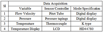
The following sensors/data acquisition modules were used to measure the system variables:
 |
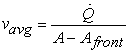
The working fluid for the experiments was taken as air. The average effective velocity of the flow impinged on the fin structures was calculated as 4
 |
Flow Reynolds number had been calculated as
 |
The system Nusselt number had been calculated as
 |
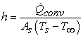
Hence, the convective heat transfer coefficient:
 |
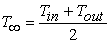
and the bulk temperature of the fluid within the system:
 |
The thermal resistance is calculated as:
 |
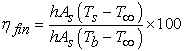
Fin efficiency,  is defined as the ratio of actual heat transfer rate from the fin to the ideal heat transfer rate from the fin if the entire fin were at base temperature.
 |
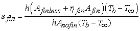
Fin effectiveness,  is the ratio of heat transfer from fin to heat transfer from fin base without fin
 |
The static pressure drop across the fin arrays  are calculated from the wind tunnel data acquisition system. The dimensionless pressure drop
  is calculated as
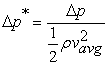 |
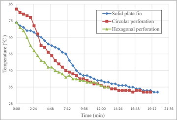
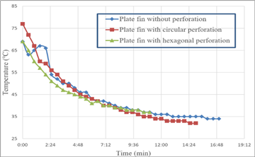
Figure 5 presents the cooling rate of plate fins at 4 ms-1 inflow. We get the result that solid plate fin without any perforation takes almost 20 minutes for reaching the room temperature; plate fin with circular perforation needs almost 18 minutes, plate fin with hexagonal perforation needs 13 minutes.
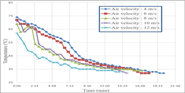
The cooling rate of different plate fins at 6 ms-1 are presented in Figure 6. The solid plate fin without any perforation takes almost 17 minutes for reaching the room temperature; plate fin with circular perforation needs almost 16 minutes, plate fin with hexagonal perforation needs 12 minutes.

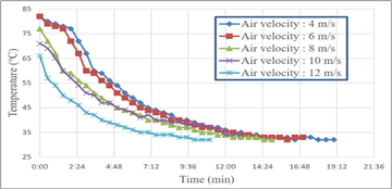
Figure 7 presents the cooling rate of different plate fin configurations at 8 ms-1 inflow. From the graph, we find that the solid plate fin without any perforation takes almost 17 minutes for reaching the room temperature; plate fin with circular perforation needs almost 15 minutes, plate fin with hexagonal perforation needs 11 minutes.
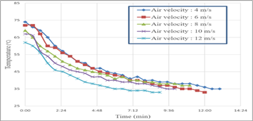
The cooling rate of different plate fins at 10 ms-1 are presented in Figure 8. The solid plate fin without any perforation takes almost 15 minutes for reaching the room temperature; plate fin with circular perforation needs almost 13 minutes, plate fin with hexagonal perforation needs 10 minutes.
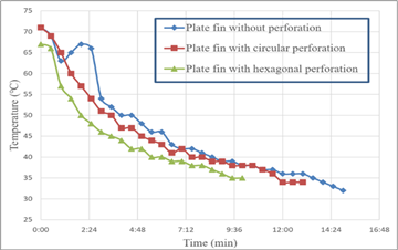
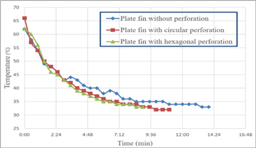
Figure 9 presents the cooling rate of different plate fin configurations at 12 ms-1 inflow. The solid plate fin without any perforation takes almost 14 minutes for reaching the room temperature; plate fin with circular perforation needs almost 11 minutes, plate fin with hexagonal perforation needs 8 minutes.
The results presented in Figure 5 – Figure 9 attest that the plate fin arrays with hexagonal perforations are the most effective variant. This is owing to the increased heat transfer area for the hexagonal perforations. The plate fin arrays with circular perforations are the second most effective variant. Both perforated fin array types show improved performance when compared to the solid plate fin arrays. As expected, the increase in flow rate results in a higher convective heat transfer for all variants.
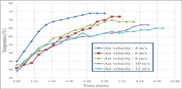
Figure 10 depicts the heating rate of the air past the solid plate fins. The graph shows that the time needed for the temperature of base plate to come close to the ambient temperature is gradually decreased with the increase of air velocity for the solid plate fin. The input temperature remains nearly constant throughout the cooling time for all the air velocity. The time required for the temperature of output to become close to the input ambient temperature for 4 ms-1, 6 ms-1, 8 ms-1, 10 ms-1, and 12 ms-1 was 20 minutes, 18 minutes, 17 minutes, 15 minutes, and 14 minutes respectively.
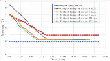
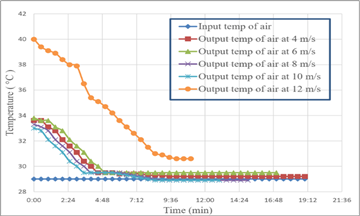
Figure 11 depicts the heating rate of the air past the plate fins with circular perforations. The time required for the temperature of output to become close to the input ambient temperature for 4 ms-1, 6 ms-1, 8 ms-1, 10 ms-1, and 12 ms-1 was 19 minutes, 16 minutes, 15 minutes, 13 minutes, and 11 minutes respectively.
Figure 12 depicts the heating rate of the air past the plate fins with hexagonal perforations. The time required for the temperature of output to become close to the input ambient temperature for 4 ms-1, 6 ms-1, 8 ms-1, 10 ms-1, and 12 ms-1 was 13 minutes, 12 minutes, 11 minutes, 10 minutes, and 8 minutes respectively.
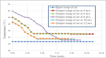
The results shown in Figures 10-12 attest that the plate fins with hexagonal perforations have the highest heat transfer rate, followed by the variations with the circular perforations. Also, the flow rates with 4 ms-1 and 6 ms-1 velocity rendered the highest temperature difference between incoming and outgoing air temperature. For higher flow rates, the differences between inflow and outflow air temperature are minimal.
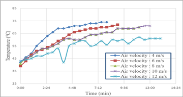
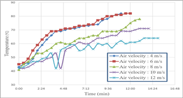
The heating time required for the different plate fin configurations under varying flow rates are depicted in Figure 13 (a, b, c). The results for solid plate fins are presented in Figure 13 (a), and for plate fins with circular and hexagonal perforations are presented in Figure 13 (b), and Figure 13 (c) respectively. The fin arrays with hexagonal perforations take the longest time to reach equilibrium temperature, followed by those with circular perforations and solid plated fin arrays. For increasing flow rate of air, the forced convective heat transfer increases, thus increasing the time to achieve equilibrium temperature at the base plate of the different fin arrays.
A reversed trend is observed in the cooling time of the base plates for the different plate fin array configurations, which are presented in Figure 14 (a, b, c). Hence, the results for solid plate fin arrays are presented in Figure 14 (a), and those for plate fins with circular and hexagonal perforations are presented in Figure 14 (b) and Figure 14 (c) respectively. Increasing flow rate of air assist the heat convection, thus reducing the time required for the base plates to cool down for all combinations of plate fin arrays.
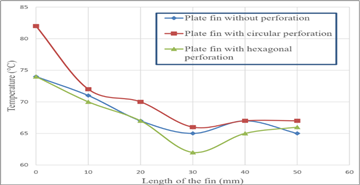
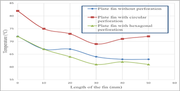
The temperature distributions along the fin surfaces of different plate fin configurations under varying flowrates are presented in Figure 15 (a, b, c, d, e). The results show a general trend of decreasing surface temperature along the length of the fins.


The effect of Reynolds number for different kind of plate fins on fin effectiveness is shown in Figure 16. The result suggests that fin effectiveness for plate fin with hexagonal perforation is the highest followed by that with circular perforation. Both perforated plate fins exhibited higher fin effectiveness than the solid plated fin. The highest fin effectiveness values for the perforated variants are found within the Reynolds number range of 3-4 x 10⁴.

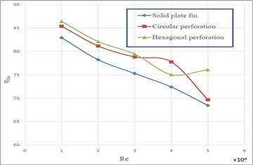
The effect of Reynolds number for different kind of plate fins on fin efficiency is shown in Figure 17. The result suggests that fin efficiency for plate fin with hexagonal perforation is comparatively higher than the others. Also evident from the result that, the fin efficiency decreases with increasing Reynolds number. This is due to the fact that the base temperature decreases with higher flow rate.
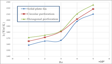
The effect of Reynolds number for different kind of plate fins on convective heat transfer coefficient is shown in Figure 18. The result suggests that convective heat transfer coefficient for plate fin with hexagonal perforation is comparatively higher than the other plate fin arrays. It is also evident from the results that, the convective heat transfer coefficient is increased with the increasing Reynolds number.
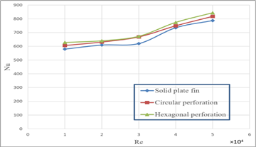
The effect of Reynolds number for different kind of plate fins on Nusselt number is shown in Figure 19. The result suggests that Nusselt number for plate fin with hexagonal perforation is comparatively higher, followed by that with circular perforation and of solid plated fins. The Nusselt number is increased with the increasing Reynolds number for all variants of plate fin arrays.
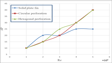
The effect of Reynolds number for different kind of plate fins on pressure drop is shown in Figure 20. The result suggests that pressure drop for plate fin with hexagonal perforation is comparatively higher than any other ones in this graph. The pressure drop is increased with the increasing Reynolds number and also with the perforation due to increased pressure loss factor.
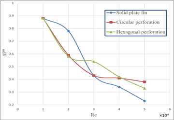
The effect of Reynolds number for different kind of plate fins on dimensionless pressure drop is shown in Figure 21. The result suggests that dimensionless pressure drop for plate fin with hexagonal perforation is comparatively lower than the solid plated fins at low Reynolds number range. The dimensionless pressure drop is decreased with the increasing Reynolds number. At higher Reynolds number, the value of ∆p* is higher for the plate fins with hexagonal perforations when compared to the value of the solid plated fin.
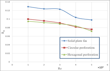
The effect of Reynolds number for different kind of plate fins on thermal resistance is shown in Figure 22. The result suggests that the thermal resistance for plate fin with hexagonal perforation is comparatively higher than the perforated variants. The thermal resistance is increased with the increasing Reynolds number.
In this work two different perforations are tested on plate fin along with solid plate fin variant to observe different parameters viz. convective heat transfer co-efficient, Nusselt Number, thermal resistance, efficiency and effectiveness with varied Reynolds Number. The Nusselt number, convective heat transfer coefficient and pressure drop increase with increasing Reynolds number for all fins. Heat transfer is more at higher air velocities. So forced convection is much more desirable for efficient cooling. Perforated fins show higher values of  and
and  , and lower values of pressure drop than solid fins. Between circular and hexagonal perforation, in hexagonal perforation the value of
  and
and  is observed to be higher. The values of thermal resistance, efficiency, effectiveness and dimensionless pressure drop, in general, decrease with the increasing Reynolds number for all the fins.
This paper documents the experimental setup, data acquisition system and the experimental investigation on the effect of having a different perforation on plate fins. Bulk characteristic flow numbers are calculated using the flow variables measured during the experiments. The following conclusions can be drawn from the experimental results presented in this paper. The inclusion of perforation enhances the effectiveness of the plate fin system. It is seen that the effect of increased flow rate increases the convective heat transfer rate. The efficiency of the system drops down with increasing Reynolds number. Overall, the plate fin with hexagonal perforations performed the best, followed by the plate fin with circular perforation. The results presented in this paper should be used as reference for future work, which should include analytical and numerical calculations, as well as intensive boundary layer flow measurement to understand the dynamics of such system. From practical point of view, hexagonal perforated plate fins should enhance heat transfer rate in forced convective heat transfer applications.
 : Total flow-restricting area
 : Cross sectional area of wind tunnel test section
 : Total heat transfer area of the fin array
 : Total heat transfer area of the finless portion
 : Total heat transfer area when there are no fins
 : Total heat transfer area
 : Hydraulic diameter of wind tunnel test section
 : Convective heat transfer coefficient of the flow
 : Characteristics length of fin
 : Nusselt number
 : Volumetric air flow rate
 : Convective heat transfer rate
 : Measured flow velocity inside test section
 : Average effective wind velocity
 : Kinematic viscosity of fluid
 : Thermal conductivity of fluid
 : Thermal resistance
 : Average base temperature
 : Average surface temperature of fin array
 : Average bulk temperature of fluid
 : Inlet temperature of fluid
 : Outlet temperature of fluid
 : Fin effectiveness
 : Fin efficiency
 : Static pressure drop across fin arrays
 : Dimensionless static pressure drop across fin arrays
| [1] | D.E. Metzger, C.S. Fan, S.W. Haley, Effects of pin shape and array orientation on heat transfer and pressure loss in pin fin arrays, J. Eng. Gas Turbines Power 106 (1984) 252-257. | ||
| In article | View Article | ||
| [2] | Yunus A. Çengel, 2004, “Heat Transfer- A Practical Approach”, SI units 3rd Edition, Tata McGraw Hill Co., Pg. No.: 159. | ||
| In article | |||
| [3] | Akshendra Soni, Study of Thermal Performance between Plate-fin, Pin-fin and Elliptical Fin Heat Sinks in Closed Enclosure under Natural Convection, International Advanced Research Journal in Science, Engineering and Technology, Vol. 3, Issue 11, November 2016. | ||
| In article | |||
| [4] | Mehedi Ehteshum, Mohammad Ali, Md. Quamrul Islam, Muhsia Tabassum, Thermal and hydraulic performance analysis of rectangular fin arrays with perforation size and number, 6th BSME International Conference on Thermal Engineering (ICTE 2014). | ||
| In article | View Article | ||
| [5] | Bayram Sahin, Alparslan Demir, Performance analysis of a heat exchanger having perforated square fins, ELSEVIER, Applied Thermal Engineering 28 (2008) 621-632. | ||
| In article | View Article | ||
| [6] | A. A. Bhuiyan, A. K. M. Sadrul Islam, M. R. Amin, “Numerical study of 3D thermal and hydraulic characteristics of wavy fin-and-tube heat exchanger”, Frontiers in heat and mass Transfer (FHMT) 3 - 033006, 2012. | ||
| In article | View Article | ||
| [7] | A. A. Bhuiyan, M. R. Amin, A. K. M. Sadrul Islam, “Three-Dimensional Performance Analysis of Plain Fin Tube Heat Exchangers in Transitional Regime”, Applied Thermal Engineering, Vol 50, Issue 1, pp 445-454, 2013. | ||
| In article | View Article | ||
| [8] | A. A. Bhuiyan, M. R. Amin, R. Karim, A. K. M. Sadrul Islam, “Plate fin and tube heat exchanger modeling: Effects of performance parameters for turbulent flow regime”, International Journal of Automotive and Mechanical Engineering (IJAME), 9(1), pp. 1768-1781, 2014. | ||
| In article | View Article | ||
| [9] | Giovanni Tanda, “Heat transfer and pressure drop in a rectangular channel with diamond-shaped elements”. In International Journal of Heat and Mass Transfer Volume 44, Issue 18, September 2001, Pages 3529-3541. | ||
| In article | View Article | ||
Published with license by Science and Education Publishing, Copyright © 2023 Md Lutfor Rahman and Irfan Ahmed
![]() This work is licensed under a Creative Commons Attribution 4.0 International License. To view a copy of this license, visit
http://creativecommons.org/licenses/by/4.0/
This work is licensed under a Creative Commons Attribution 4.0 International License. To view a copy of this license, visit
http://creativecommons.org/licenses/by/4.0/
| [1] | D.E. Metzger, C.S. Fan, S.W. Haley, Effects of pin shape and array orientation on heat transfer and pressure loss in pin fin arrays, J. Eng. Gas Turbines Power 106 (1984) 252-257. | ||
| In article | View Article | ||
| [2] | Yunus A. Çengel, 2004, “Heat Transfer- A Practical Approach”, SI units 3rd Edition, Tata McGraw Hill Co., Pg. No.: 159. | ||
| In article | |||
| [3] | Akshendra Soni, Study of Thermal Performance between Plate-fin, Pin-fin and Elliptical Fin Heat Sinks in Closed Enclosure under Natural Convection, International Advanced Research Journal in Science, Engineering and Technology, Vol. 3, Issue 11, November 2016. | ||
| In article | |||
| [4] | Mehedi Ehteshum, Mohammad Ali, Md. Quamrul Islam, Muhsia Tabassum, Thermal and hydraulic performance analysis of rectangular fin arrays with perforation size and number, 6th BSME International Conference on Thermal Engineering (ICTE 2014). | ||
| In article | View Article | ||
| [5] | Bayram Sahin, Alparslan Demir, Performance analysis of a heat exchanger having perforated square fins, ELSEVIER, Applied Thermal Engineering 28 (2008) 621-632. | ||
| In article | View Article | ||
| [6] | A. A. Bhuiyan, A. K. M. Sadrul Islam, M. R. Amin, “Numerical study of 3D thermal and hydraulic characteristics of wavy fin-and-tube heat exchanger”, Frontiers in heat and mass Transfer (FHMT) 3 - 033006, 2012. | ||
| In article | View Article | ||
| [7] | A. A. Bhuiyan, M. R. Amin, A. K. M. Sadrul Islam, “Three-Dimensional Performance Analysis of Plain Fin Tube Heat Exchangers in Transitional Regime”, Applied Thermal Engineering, Vol 50, Issue 1, pp 445-454, 2013. | ||
| In article | View Article | ||
| [8] | A. A. Bhuiyan, M. R. Amin, R. Karim, A. K. M. Sadrul Islam, “Plate fin and tube heat exchanger modeling: Effects of performance parameters for turbulent flow regime”, International Journal of Automotive and Mechanical Engineering (IJAME), 9(1), pp. 1768-1781, 2014. | ||
| In article | View Article | ||
| [9] | Giovanni Tanda, “Heat transfer and pressure drop in a rectangular channel with diamond-shaped elements”. In International Journal of Heat and Mass Transfer Volume 44, Issue 18, September 2001, Pages 3529-3541. | ||
| In article | View Article | ||


