Extra-large double-walled cryogenic storage tanks that are used to store LPG (Liquefied Petroleum Gas) in the low temperature are known as Full Containment Tank (FCT). The tank design shall include normal operating conditions, such as liquid hydrostatic loads and thermal loads, and abnormal conditions, such as seismic loads. The detailed and accurate design of an FCT subjected to seismic conditions combined with thermal and hydrostatic loads is a complex analysis. In the present paper, Finite Element Method (FEM) simulation is a feasible and efficient method to predict stresses and displacements of the FCT 3-D model. Two analyses, seismic analysis, and combined thermal-seismic analysis, are run to compare the results and compute thermal effects on the seismic responses. The first model of FCT is subjected to hydrostatic loads and seismic loads with slashing liquid waves, while the second model of FCT is analyzed with hydrostatic loads and thermal stresses. The resulting displacements are applied to the tank model elements as initial conditions to run the model for seismic analysis. Comparing simulation results show that thermal stress effects on the final seismic responses are not ignorable.
Liquefied Petroleum Gas (LPG) has a cryogenic temperature range of -45°C to -7°C to ensure the minimum storage volume when stored in an LPG tank. Of the various types of LPG storage tanks, the total containment, above-ground type, is now employed worldwide; thus, it is selected as the main structural type considered in this study. A typical full containment tank has a double safety system consisting of an outer concrete tank and an inner steel tank. In addition, several types of insulations between the outer tank and the inner tank, bottom, and wall are used to maintain the required boil-off gas rate 1. BS7777 standard is applied to design full containment tanks. This standard presents imposed loads on the structure during its lifetime, especially earthquake analysis. The common failure modes of storage tanks are tank wall buckling, local buckling at the upper part of the tank wall due to liquid sloshing, and joint connections fracture (Rinne, 1967, 2). After the tanks were severely damaged in the Alaska earthquake 2, the studies were promoted to analyze tank wall elastic behavior during earthquakes in detail. In 1981, Haroun and Housner 3 developed a model that accounted for earthquake effects on an elastic tank wall. In the Haroun-Housner model, the dynamic interaction of liquid and the tank wall is applied with the assumption of flexible impulsive pressure components. Fischer et al. 1991 report that large tanks' most common failure mode does not result from the overturning moment of higher 1st-order mode 4. The tanks with rigid wall designs that failed in Alaska’s seismic activities have been researched to improve the design (Korkmaz, et al., 2011 5; Paolacci, et al., 2013, 6). The elasticity of tank walls is considered in seismic load analysis in the following papers (Haroun, 1983, 7; Veletsos and Kumar, 1986, 8). Christovasilis and Whittaker (2008) analyzed the conventional and isolated LNG Tanks using mechanical analogs 9. In addition, the exterior concrete shell imposed by low-temperature and seismic effects has been investigated separately by Marcus N. T. Gillard, et al., 2012, 10.
In general, the dynamic design of full containment tanks has yet to be studied with the cryogenic thermal condition simultaneously, while realistic thermal analyses are of primary importance for a successful design. Some recent studies pursue a temperature analysis of the LNG/LPG tanks (Watanabe, 2003, 11; Chen, 2004, 12). Also, a consistent thermal analysis has been applied in the design of LNG storage tanks by Se-Jin et al. (2007) 13.
With advancements in structural finite element programs, more detailed analyses of storage tanks are available now. Recently, some finite element (FE) studies have been performed on thermal analysis of the shell stiffeners of double steel wall LNG storage tanks (Xiao and Yuan, 2012, 14), buckling pressure in double wall cryogenic storage tanks (Nemati and Ghanbari, 2014, 15), and thermal stress analysis of concrete wall of LNG tanks during construction period by Ximei Zhai et al. (2016) 16. All mentioned FE models include only the main components of storage tanks, such as the wall, roof, bottom, or foundation. Rulin Zhang et al. (2020) investigated the effects of multi-directional elements of ground motion in an unanchored steel storage tank in ANSYS 17.
The tank analyzed in the present study, is a 35,000 m3 full containment storage tank. The inner steel tank with a diameter, DS, of 42.25 m and a total height, HS, of 27.47 m is fully anchored to a concrete slab. The tank is filled with liquid butane to a height of 26 m (95% of the inner tank height). The density of LPG, ρL, is 601 kg/m3, and its temperature is -15°C. The maximum ambient temperature is 50°C. The inner steel tank is made of a 9% nickel steel plate, which is usually used for cryogenic temperature tanks, with elastic modulus, Es,200 GPa, Poisson’s ratio, νs,0.3, and density, ρs,7850 kg/m3. The inner steel tank consists of seven courses. The thickness and height of each course are shown in Table 1. Thicker parts are located in lower tank levels because of liquid hydrostatic pressure.
The outer concrete tank protects the inner steel tank from external loads. The outer tank is made of post-tensioned reinforced concrete. The outer tank geometry dimensions are tank height, LC, 29.3 m; inner diameter, DC, 44.44m; concrete thickness, tC,0.6m; concrete wall density, ρc,2500 kg/m3; elastic modulus, EC, 30 GPa; and Poisson’s ratio, υC, 0.2. The light concrete density of the outer tank bottom slab, ρLC, is 120 kg/m3 with elastic modulus, ELC, 1.5GPa and Poisson's ratio, υLC,0.2.
Figure 1 shows various types of insulation layers between the two tanks. The expanded perlite is attached to the outer tank's inner wall, and the inner tank's outer wall is lined with resilient felt that provides elastic properties for the perlite and prevents it from settling. This elasticity is essential due to temperature-induced tank shrinkage. The wall insulation material properties are density, ρP,65 kg/m3; elastic modulus, EP, 80 MPa; and Poisson’s ratio, υP, 0.2. Foam glass HLB800 is used for the bottom insulation between the two tanks. The bottom insulation properties are density, ρHLB, 120 kg/m3; elastic modulus, EHLB, 1 GPa; and Poisson’s ratio, υHLB, 0.24.
Additional details on geometry dimensions can be found in Figure 2.

The 3D finite element model is employed in two analyses using the configuration and material properties specified in section 2. The first finite element model is analyzed by applying seismic loading without initial thermal conditions, and the second model considers applying seismic loading with initial thermal conditions. Figure 3 shows the sequences of creating and running the tank model for two scenarios, seismic analysis and thermal-seismic analysis, by finite element method in Ansys.

As the LPG tank contains cryogenic liquid, realistic conditions for thermal analyses are of primary importance for a successful design. In order to predict the inner face temperatures of the wall or the bottom slab while considering the effect of insulation layers, we should convert insulation into equivalent concrete with the condition that the heat flux is equal even after the conversion. The equivalent concrete thickness (tci, eq) corresponding to an i’th insulation is obtained from Equation (1) 13.
 | (1) |
Similar to the solution results of the one-dimensional heat conduction equation under the steady state condition, the temperature gradient is linear through all the thicknesses, including the temperature distribution through the equivalent concrete thicknesses. As a result, the inner face temperature (Tg) can be derived as in Equation (2) 13.
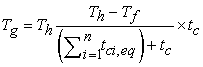 | (2) |
Parameters of the above relation are shown in Figure 4.


Haroun-Housner model is simplified for broad tanks; in such a case, the contribution of the higher vibration modes of the wall can be neglected, and the distributions of the impulsive and flexible pressure are almost coincident. Therefore, the effects of the impulsive and flexible components may be globally evaluated in terms of the absolute acceleration of a simple oscillator with mass mi and stiffness ki. When the higher modes of convective motion are also neglected, the dynamics of a broad tank may be studied using two simple oscillators with mi, the effective impulsive portion of the liquid mass and mc, the effective convection (sloshing) part of the liquid mass and periods Ti and Tc (Figure 5).
This model introduces the simple equations for the vertical circular tanks subjected to horizontal excitation 18. In the Haroun-Housner model, the equations are:
Weights of accelerating liquid
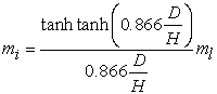 | (3) |
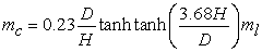 | (4) |
Structural period of vibration
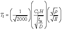 | (5) |
 | (6) |
 | (7) |

The ground motion from the earthquake on the surface can be defined by six components; three translational parts and three rotational parts. The translational components include two components in the horizontal plane, and one in the vertical direction. The rotation about the horizontal axis leads to rising rocking, while the rotational component about the out the vertical axis generates torsional effects even in symmetrical buildings. Due to the evident and significant contribution of ground shakings to the overall response of structures, rocking and torsional components of these motions resulting from strong earthquakes are recently subjected to widespread research by engineering and research communities 17.
Full transient analysis is performed to determine the dynamic response of the tanks subjected to three and six components of the earthquake. For this purpose, three translational components of Kern County earthquake are used to derive the time histories of the corresponding rotational components 19. The time history of X, Y, and Z components for the Kern County earthquake is shown in Figure 6 19.
3.3. Hydrodynamic ModelThe principles of mass continuity and linear momentum can explain the behavior of the fluid inside the tank. The vector form of the momentum equation is given as Equation (8), derived from the Navier-Stokes equation.
 | (8) |
In case μ is neglected (μ=0), s,o the Euler equation is derived as Equation (9):
 | (9) |
By considering only the hydraulic pressure, Equation (10) is acquired:
 | (10) |
Finally, by assuming linear compressibility of the fluid and non-rotational fluid movement and by using the principles of the mass continuity and linear momentum, Equation (11), known as the Helmholtz equation, is derived:
 | (11) |
To solve this differential equation, suitable boundary conditions must be defined. The boundaries are the free surface of the liquid, the boundary between the liquid and the tank wall, and the boundary between the liquid and tank bottom.
The equation can be utilized for deriving free surface boundary conditions. Assuming surface tension is negligible, Equation (12) is acquired for the liquid-free surface:
 | (12) |
Since the tank wall is sealed, it is assumed that no slip flow of containing liquid exists through the tank wall, which in turn results in Equation (13):
 | (13) |
Finally, with the assumption of suitable sealing of the tank bottom, Equation (13) is also applicable for the boundary between containing liquid and the tank bottom slab.
Response-history analysis of finite element (FE) of a conventional LPG tank can solve the equations presented in section 3 for the tank with the specifications mentioned in section 4. ANSYS, an FE code that combines structural and fluid simulation capabilities, is used to model a vertical cylindrical tank in the three-dimensional space.
4.1. FEM Simulation StrategyANSYS was used to model the LPG tank specified in section 2 in 3-D with all components, including the inner wall, outer concrete wall, bottom, roof, insulation, and containing liquid (Figure 7).

In thermal-structure analysis, SHELL131 and SHELL181 are used to model the inner steel tank. SHELL131 element of ANSYS is a 4-node 3D layered shell element with in-plane and through-thickness thermal conduction capability. The element has four nodes with up to 32 temperature degrees of freedom. This element is suitable for three-dimensional, steady-state, and thermal analysis. For seismic analysis, SHELL131 should be replaced by SHELL181. Computed thermal stresses from thermal analysis on the steel tank with SHELL131 are considered initial condition inputs for structural analysis on the steel tank with SHELL181. SHELL181 is a four-node element with six degrees of freedom at each node: translations in the x, y, and z directions and rotations about the x, y, and z-axes. The element is well-suited for linear, significant rotation, and large-strain nonlinear applications. The change in shell thickness is accounted for in nonlinear analyses. For thermal-structural analysis, SOLID70 and SOLID185 elements are used to model the outer tank, including the concrete wall of the tank, the concrete bottom slab, the concrete dome roof, and all insulations applied in the wall and bottom of the tank. SOLID70 has a 3-D thermal conduction capability. The element has eight nodes with a single temperature degree of freedom at each node. The element is applicable to a 3-D, steady-state, or transient thermal analysis. The element also can compensate for mass transport heat flow from a constant velocity field. For structural analysis, the SOLID70 element should be replaced by SOLID185. Computed thermal stresses from thermal analysis on the outer tank with SOLID70 are considered initial condition inputs for structural analysis on the steel tank with SOLID185. SOLID185 is used for 3-D modeling of solid structures. It is defined by eight nodes having three degrees of freedom at each node: translations in x, y, and z directions. The element has plasticity, hyper-elasticity, large deflection, and large strain. It also has mixed formulation capability for simulating deformations of nearly incompressible elastoplastic and fully incompressible hyper-elastic materials.
The fluid, Butane, domain was modeled by three-dimensional, eight-nodded, 24 degrees of freedom fluid elements (FLUID80). These elements have 3 degrees of freedom at each node, displacement in three directions. The interaction between the tank and the fluid was addressed by adequately coupling the nodes in the common faces of these two domains in the radial direction. The fluid cannot separate from the tank wall but can move in transverse directions and apply only normal pressures on the tank wall.
In this tank, the fluid is in contact with the inner steel tank wall in the radial direction and in contact with the inner steel tank floor in the vertical direction. Steel tank wall and floor elements are coupled to the fluid elements in the boundary so that the fluid does not separate from the wall and floor of the tank. Also, the wall and floor components, including steel parts, concrete parts, and insulations of both tanks, are entirely closed together in the boundaries. Finally, the bottom slab of the outer tank is fixed to the ground. Only seismic loads are imposed on the tank in the first modeling strategy (structural analysis without thermal analysis effects). So SHELL181 for inner steel tank components, SOLID185 for concrete outer tank and insulation elements, and FLUID80 for liquid are applied to compute the structural stresses and deformations. In the second modeling strategy (structural analysis after thermal analysis effects), seismic and thermal loads are applied. The tank is modeled by thermal element, SHELL131, and structural element, SHELL181, for inner steel tank components; thermal element, SOLID70, and structural element, SOLID185, for concrete outer tank and insulations elements and FLUID80 for seismic analysis of liquid. The SHELL131 and SOLID70 elements were automatically replaced by SHELL181 and SOLID185 in the ANSYS software, as described above.
The seismic loads are imposed on all nodes of the concrete bottom elements of the outer tank. Thermal stresses are applied by setting the temperature of the internal liquid elements at -15°C. Finally, the tri-angular hydrostatic loads are imposed on the merged nodes of interconnection elements between the inner wall and the nodes of containing liquid elements.
4.2. Computed ResultsTo present FEM analysis results, four sections on LPG tanks are specified: section A (inner tank wall), section B (top ring beam), section C (top of inner tank wall), and section D (concrete outer tank wall). The locations of the sections are shown in Figure 7.
The counters of Von Mises stress and the displacement graphs of above four sections are extracted from FE analysis of the first model, the tank imposed only by seismic loads, and the second model, the tank imposed with both thermal and seismic loads.
The counter of Von Mises stress of the storage tank for the first model is shown in Figure 8. The maximum stress, 47.2 MPa, is provided at 7.215m height from the bottom slab of the tank. Figure 9 shows the counter of Von Mises stress of the storage tank for the second model. The maximum stress, 50.7 Mpa, is obtained at 8.215m height from the bottom slab of the tank. The time history graphs of von Mises stress for both models in section D are shown in Figure 10. Tensile stresses, positive numbers, at section D of the storage tank in the first model are converted to compression stresses, negative numbers, in the second model.


The x-direction displacements of the tank at sections A, B, and C for both seismic and thermal-seismic analyses are in Figure 11. In all three sections, the displacements in the second analysis, seismic analysis with initial thermal effects, are more than those resulting from seismic analysis without thermal effects. The maximum and minimum absolute displacement values and the average amount of displacements at each section of A, B, and C in the time history shown in Figure 11 for both models are tabulated in Table 2. Also, the differences between the average amounts of displacements for each model are included in the table. The most significant difference in average displacement is related to section B, 10.21 mm, which shows that the analyzed tank with thermal-seismic loads presents more deflection than the tank with only seismic loads.
In addition to the comparison between results computed from both FE analyses, seismic analysis, and thermal-seismic analysis, the comparison between the results computed from the FEM model and the loads calculated from common standards, ACI 350.3R-01, seismic design of liquid-containing concrete structures and commentary, and API650, welded tanks for oil storage, are useful. The shear forces of LPG tanks subjected to Kern County earthquake calculated by ACI 350.3R-01, API650, and the FEM analyses are shown in Table 3. The tank base shear stress calculated from ACI 350.3R-01 and API650 standards is 6.9 MN and 4.6 MN, respectively, while 6.2 MN is computed from FEM. The value estimated by FEM is between the numbers calculated from both standards. It shows a 10.4% difference from ACI 350.3R-01 and a 34.8% difference from API 650.

A study of the thermal-seismic and seismic response of the LPG tank, considering all layers (a combination of concrete, steel, and insulation layers), has been conducted. Since LPG tanks should safely contain cryogenic LPG (Liquefied Petroleum Gas), combined thermal and seismic analysis is performed to assess the safety (stresses) or serviceability (deformations) of a sample storage tank case. The results of two modeling strategies (imposing seismic analysis without considering thermal effects on tank structure and combined seismic-thermal analysis) are compared. The following conclusions may be drawn from this study:
| [1] | Long, B., Garner, B. (2004) "Guide to storage tanks & Equipment", Professional Engineering Publishing, ISBN: 978-1-860-58431-2. | ||
| In article | |||
| [2] | Rinne, J. E. (1967) “Oil storage tanks in Wood”, F. G. ed., Research studies-seismology and marine geology Part A, Engineering Seismology. Vol. 2 of The Prince William Sound Alaska earthquake of 1964 and aftershocks US Coast and Geod Survey Pub 10 3 p 245 252. | ||
| In article | |||
| [3] | Housner, G. W., and Haroun, M. A. (1981) “Earthquake response of deformable liquid storage tanks.” Journal of Applied Mechanics, Vol. 48, No. 2, pp. 411-418. | ||
| In article | View Article | ||
| [4] | Fischer, F. D., Rammerstorferf, F. G., and Scharf, K. (1991) “Earthquake Resistant Design of Anchored and UnanchoredLiquid Storage Tanks Under Three-Dimensional EarthquakeExcitation. Structural Dynamics, pp. 317-371. | ||
| In article | View Article | ||
| [5] | Korkmaz, K. A., Sari, A., and Carhoglu, A. I. (2011). “Seismic risk assessment of storage tanks in Turkish industrial facilities.” Journal of Loss Prevention in the Process Industries, Vol. 24, No.4, pp. 314-320. | ||
| In article | View Article | ||
| [6] | Paolacci, F., Giannini, R., and De Angelis, M. (2013). “Seismic response mitigation of chemical plant components by passive control techniques.” Journal of Loss Prevention in the Process Industries, Vol. 26, No.5, pp.924-935. | ||
| In article | View Article | ||
| [7] | Haroun, M. A., (1983). “Vibration studies and tests of liquid storage tanks.” Earthquake Engineering and Structural Dynamics, Vol. 11, No. 2, pp. 179-206. | ||
| In article | View Article | ||
| [8] | Veletsos, A. S., and Kumar, A. (1986). “Dynamic response of vertically excited liquid storage tanks.” Proc. 8th World. Conf. on Earthquake Engineering, San Francisco, USA, pp. 453-460. | ||
| In article | |||
| [9] | Christovasilis, I. P., and Whittaker, A. S. (2008). “Seismic analysis of conventional and isolated LNG tanks using mechanical analogs.” Earthquake Spectra, Vol. 24, No. 3, pp. 599-616. | ||
| In article | View Article | ||
| [10] | Gillard, M. N. T.,Mathew J. L., , and William A. S. (2012), “Liquefied natural gas tank analysis: cryogenic temperatures and seismic loading.” Proceedings of the Institution of Civil Engineers-Engineering and Computational Mechanics, Vol.165, NO.1, pp. 49-56. | ||
| In article | View Article | ||
| [11] | Watanabe, N., Endo, H., Xuehui, A., Nakano, M., and Aoki, H. (2003), “Application of non-linear analysis to the structural design of an LNG In-ground tank.”, JSCE Journal of Construction Management and Engineering, (Japan Society of Civil Engineers), Vol. 2003, No. 742, pp. 87-100. | ||
| In article | View Article | ||
| [12] | Chen, Q.S., Wegrzyn, J. and Prasad, V. (2004), “Analysis of temperature and pressure changes in liquefied natural gas (LNG) cryogenic tanks.”, Cryogenics, Vol. 44, No. 10, pp. 701-709. | ||
| In article | View Article | ||
| [13] | Se-Jin Jeon, Byeong-Moo Jin, and Young-Jin Kim, (2007), “Consistent thermal analysis procedure of LNG storage tank.”, Structural Engineering and Mechanics, Vol. 25, No. 4, pp. 445-466. | ||
| In article | View Article | ||
| [14] | Zhang, X. C., and Cai, Y. Q., (2012), “Thermal Analysis on the Shell Stiffeners of Double Steel Wall LNG Storage Tank.” Applied Mechanics and Materials, Vols. 105-107, pp. 403-407. | ||
| In article | View Article | ||
| [15] | Nemati, H., and Ghanbari, G, (2014), “buckling pressure in double wall cryogenic storage tank” Emirates Journal for Engineering Research, Vol. 19, No. 1, pp. 43-48. | ||
| In article | |||
| [16] | Zhai. X., Wang. Y. and Wang. H. (2016), “Thermal stress analysis of concrete wall of LNG tank during the construction period.” Materials and Structures, Vol. 49, pp. 2393-2406. | ||
| In article | View Article | ||
| [17] | Zhang, R., Chu, Sh., Sun, K., Zhang, Zh., and Wang, H. (2020) "Effect of the Directional Components of Earthquakes on the Seismic Behavior of an Unanchored Steel Tank." Applied Sciences, Vol. 10, No. 16. | ||
| In article | View Article | ||
| [18] | Zhang, R., Weng, D. (2014) "Assessment of the seismic effect of insulation on extra-large cryogenic liquid natural gas storage tanks." Journal of Loss Prevention in the Process Industries, Vol. 30, pp. 9-16. | ||
| In article | View Article | ||
| [19] | Clough, R., and Penzin, J. (1993) “Dynamics of Structures”, 2nd edition, McGraw-Hill Inc. | ||
| In article | |||
Published with license by Science and Education Publishing, Copyright © 2023 Mohammad T. A. Alkhamis, S. Hossein Sonbolestan and S. R. Sabbaqh
![]() This work is licensed under a Creative Commons Attribution 4.0 International License. To view a copy of this license, visit
http://creativecommons.org/licenses/by/4.0/
This work is licensed under a Creative Commons Attribution 4.0 International License. To view a copy of this license, visit
http://creativecommons.org/licenses/by/4.0/
| [1] | Long, B., Garner, B. (2004) "Guide to storage tanks & Equipment", Professional Engineering Publishing, ISBN: 978-1-860-58431-2. | ||
| In article | |||
| [2] | Rinne, J. E. (1967) “Oil storage tanks in Wood”, F. G. ed., Research studies-seismology and marine geology Part A, Engineering Seismology. Vol. 2 of The Prince William Sound Alaska earthquake of 1964 and aftershocks US Coast and Geod Survey Pub 10 3 p 245 252. | ||
| In article | |||
| [3] | Housner, G. W., and Haroun, M. A. (1981) “Earthquake response of deformable liquid storage tanks.” Journal of Applied Mechanics, Vol. 48, No. 2, pp. 411-418. | ||
| In article | View Article | ||
| [4] | Fischer, F. D., Rammerstorferf, F. G., and Scharf, K. (1991) “Earthquake Resistant Design of Anchored and UnanchoredLiquid Storage Tanks Under Three-Dimensional EarthquakeExcitation. Structural Dynamics, pp. 317-371. | ||
| In article | View Article | ||
| [5] | Korkmaz, K. A., Sari, A., and Carhoglu, A. I. (2011). “Seismic risk assessment of storage tanks in Turkish industrial facilities.” Journal of Loss Prevention in the Process Industries, Vol. 24, No.4, pp. 314-320. | ||
| In article | View Article | ||
| [6] | Paolacci, F., Giannini, R., and De Angelis, M. (2013). “Seismic response mitigation of chemical plant components by passive control techniques.” Journal of Loss Prevention in the Process Industries, Vol. 26, No.5, pp.924-935. | ||
| In article | View Article | ||
| [7] | Haroun, M. A., (1983). “Vibration studies and tests of liquid storage tanks.” Earthquake Engineering and Structural Dynamics, Vol. 11, No. 2, pp. 179-206. | ||
| In article | View Article | ||
| [8] | Veletsos, A. S., and Kumar, A. (1986). “Dynamic response of vertically excited liquid storage tanks.” Proc. 8th World. Conf. on Earthquake Engineering, San Francisco, USA, pp. 453-460. | ||
| In article | |||
| [9] | Christovasilis, I. P., and Whittaker, A. S. (2008). “Seismic analysis of conventional and isolated LNG tanks using mechanical analogs.” Earthquake Spectra, Vol. 24, No. 3, pp. 599-616. | ||
| In article | View Article | ||
| [10] | Gillard, M. N. T.,Mathew J. L., , and William A. S. (2012), “Liquefied natural gas tank analysis: cryogenic temperatures and seismic loading.” Proceedings of the Institution of Civil Engineers-Engineering and Computational Mechanics, Vol.165, NO.1, pp. 49-56. | ||
| In article | View Article | ||
| [11] | Watanabe, N., Endo, H., Xuehui, A., Nakano, M., and Aoki, H. (2003), “Application of non-linear analysis to the structural design of an LNG In-ground tank.”, JSCE Journal of Construction Management and Engineering, (Japan Society of Civil Engineers), Vol. 2003, No. 742, pp. 87-100. | ||
| In article | View Article | ||
| [12] | Chen, Q.S., Wegrzyn, J. and Prasad, V. (2004), “Analysis of temperature and pressure changes in liquefied natural gas (LNG) cryogenic tanks.”, Cryogenics, Vol. 44, No. 10, pp. 701-709. | ||
| In article | View Article | ||
| [13] | Se-Jin Jeon, Byeong-Moo Jin, and Young-Jin Kim, (2007), “Consistent thermal analysis procedure of LNG storage tank.”, Structural Engineering and Mechanics, Vol. 25, No. 4, pp. 445-466. | ||
| In article | View Article | ||
| [14] | Zhang, X. C., and Cai, Y. Q., (2012), “Thermal Analysis on the Shell Stiffeners of Double Steel Wall LNG Storage Tank.” Applied Mechanics and Materials, Vols. 105-107, pp. 403-407. | ||
| In article | View Article | ||
| [15] | Nemati, H., and Ghanbari, G, (2014), “buckling pressure in double wall cryogenic storage tank” Emirates Journal for Engineering Research, Vol. 19, No. 1, pp. 43-48. | ||
| In article | |||
| [16] | Zhai. X., Wang. Y. and Wang. H. (2016), “Thermal stress analysis of concrete wall of LNG tank during the construction period.” Materials and Structures, Vol. 49, pp. 2393-2406. | ||
| In article | View Article | ||
| [17] | Zhang, R., Chu, Sh., Sun, K., Zhang, Zh., and Wang, H. (2020) "Effect of the Directional Components of Earthquakes on the Seismic Behavior of an Unanchored Steel Tank." Applied Sciences, Vol. 10, No. 16. | ||
| In article | View Article | ||
| [18] | Zhang, R., Weng, D. (2014) "Assessment of the seismic effect of insulation on extra-large cryogenic liquid natural gas storage tanks." Journal of Loss Prevention in the Process Industries, Vol. 30, pp. 9-16. | ||
| In article | View Article | ||
| [19] | Clough, R., and Penzin, J. (1993) “Dynamics of Structures”, 2nd edition, McGraw-Hill Inc. | ||
| In article | |||


