 OPEN ACCESS
  PEER-REVIEWED
First Step to Ellipsometry

1Material Science Research Lab, S.G.T.B. Khalsa College, University of Delhi, Delhi, India
Abstract
Ellipsometry is a non-destructive, fast and accurate characterization technique used for determining the thickness and the optical constants of a material. However, this method has a drawback considering that the experimentally measured data are not meaningful in itself and one has to interpret the data based on modelling making ellipsometry dependent on the model selection, computation power/time and fitting. This makes ellipsometry, a difficult characterization method. However, it also presents a wonderful opportunity to apply the various topics taught in physics classes at undergraduate level. This paper provides the detailed insight into the self-standing film, the simplest case possible and hence the first step of ellipsometry experimentation which can be useful for substrate analysis in complex systems if the nature of the substrate is not known.
At a glance: Figures
Keywords: optics, electrodynamics, refractive index
International Journal of Physics, 2015 3 (1),
pp 8-11.
DOI: 10.12691/ijp-3-1-2
Received December 16, 2014; Revised December 30, 2014; Accepted January 03, 2015
Copyright © 2013 Science and Education Publishing. All Rights Reserved.Cite this article:
- Gupta, Yashika, and P. Arun. "First Step to Ellipsometry." International Journal of Physics 3.1 (2015): 8-11.
- Gupta, Y. , & Arun, P. (2015). First Step to Ellipsometry. International Journal of Physics, 3(1), 8-11.
- Gupta, Yashika, and P. Arun. "First Step to Ellipsometry." International Journal of Physics 3, no. 1 (2015): 8-11.
| Import into BibTeX | Import into EndNote | Import into RefMan | Import into RefWorks |
1. Introduction
Ellipsometry is an extremely sensitive, non-destructive optical technique used to optically characterize thin films and determine their thickness [1, 2]. However, the measured quantities do not explicitly give the refractive index or the film thickness. In fact the measured quantities are a function of as many as ten variables which in turn depend on the wavelength of light incident. Hence, the film parameters are decoded based on models which best mimic the physical condition of the film using optimization software [3, 4]. Commercial equipments with softwares are used by professionals, however more and more use it as a black box without understanding the physics behind it. This compounded by the fact that most universities do not teach it in detail has resulted in ellipsometry not becoming a standard characterization technique. This is surprising considering the physics and in turn the mathematics of ellipsometry is trivial and taught in standard optics courses at under-graduate level. Also, at times, popular textbooks dwell on detailed derivations (like Fresnel’s relations [5]) listing expressions without revealing where these expressions are used. The physics of ellipsometry exhibits the usage of these relations from optics [6] and hence would be of interest to students. These information are available but are in resources scattered on the web and hence difficult to compile. In this article we make an attempt to compile and introduce the physics of ellipsometry.
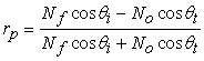
Before going into the complex mathematics associated with ellipsometry, let us understand how the instrument probes the sample. The technique involves allowing a linearly polarized light to reflect from the sample’s surface at an angle selected by the operator. The plane of polarization of the linearly polarized light is usually not in the plane of incidence. This results in two components of the incident beam of light, namely one in the plane of incidence (denoted by a subscript ‘p’) and second perpendicular to it (denoted by a subscript ‘s’) (Figure 1). The intensity and the “phase” of the reflected beam are modified. This variation strongly depends on the properties of the reflecting surface/ medium. The emerging beam of light is an elliptically polarized beam, thus giving the technique its name ‘Ellipsometry’ [7]. The experimental setup measures the reflection coefficients of the two components, namely the TE (rs = Esr/Esi) and TM (rp = Epr/Epi) modes.


 PowerPoint Slide
 Larger image(png format)


These measurements can either be made by varying the incident light’s wavelength keeping the incident angle constant [8] or by varying the incidence angle keeping the wavelength constant [9].
2. Mathematical Analysis
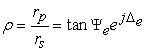
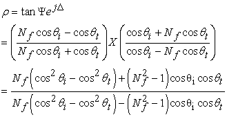
Now let us look into the mathematics involved. A variable wavelength ellipsometer returns two values for different wavelengths, namely  and Δ [4]
 | (1) |
subscripts ’e’ are added to show that these are experimentally determined. We can write rp and rs in polar form
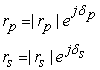 |
Where  and
and  are the magnitude of the amplitudes while
  and
and  are the phases of the respective complex reflection coefficients.

 PowerPoint Slide
 Larger image(png format)
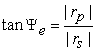
The measured  contains the information on change in intensity on reflection such that the tangent of
  gives the magnitude ratio of 'p' and 's' polarization's reflection coefficients
 |
and the angle  gives the difference between the phase shifts experienced by the two polarizations and is given as
 |
This would imply that  is a complex number. We shall revisit this idea later.
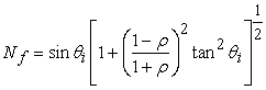
The reflection coefficients rp (for TM mode) and rs (for TE mode) are given as Fresnel’s equations in standard textbooks of optics [4, 8]:
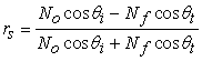 |
 | (2) |
where No is the refractive index of air and is taken as unity hereafter. Nf is the complex refractive index of the film, while  and
and  are the angle of incidence and transmittance respectively. Figure 3 shows the raw data given by a J.A. Woolam (USA) spectroscopic ellipsometer. One can immediately appreciate that the process of inferring the material properties from this is going to be involved. As a starting point we consider that the film under study is capable of standing on its own, i.e. can sustain itself without the assistance of a substrate. We can also consider the sample to be thick (as compared to the wavelength of light probing it) implying that the second boundary (film-air) is far from the air-film interface and hence will not contribute in our analysis. Few authors also call this a case of “films whose thickness are semi-infinite”

 ψ and (B) ∆ with wavelength made for a glass microscope slide used as substrates for thin films. The measurements were made for θi = 60o using a J.A. Woolam Spectroscopic Ellipsometer (USA)) PowerPoint Slide
PowerPoint Slide Larger image(png format)
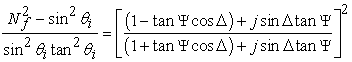
Substituting the Fresnel relations eqn (2) in eqn (1), we have
 | (3) |
Using trigonometric relation 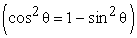 and Snell’s law
 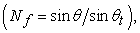 we have
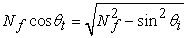 | (4) |
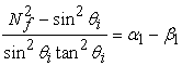
Substituting this result in eqn (3), ‘ ’ reduces to an expression in terms of incidence angle and sample’s refractive index
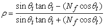 | (5) |
Since  is related to
  through Snell’s law, we have
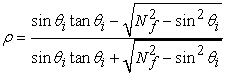 | (6) |
The angle of incidence ( ) is selected by the operator at the start of the experiment, hence the only unknown parameter is the sample’s refractive index
  . With a little bit of algebra, values of
  can be estimated from the measured ψ and ∆. Re-arranging the above equation (eqn 6), we have
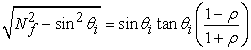 |
and finally
 | (7) |
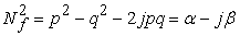
We now immediately see that since  is complex, the refractive index too has to be complex, i.e
 |
where ‘q’ is the extinction coefficient and is related to the absorption of the light in the material. In the case of self standing films, the optical constants (p,q) of the films can be estimated directly by the mathematical inversion of the basic ellipsometry equation above. Eqn (7) maybe expanded as
 |
Representing the right hand side as a compact number, we have
 |
where
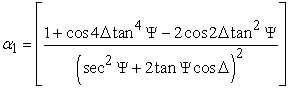 |
 |
Further simplification gives
 |
where
 |
 |
Writing the left hand side of the equation as a complex term, we have
 |
Giving
 |
 |
Setting up a quadratic equation (put  ), we get
 |
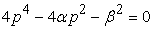 |
Giving
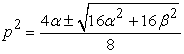 |
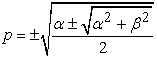 |
Of which the only physically acceptable result would be (p>0)
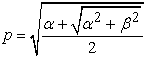 |
Using the above result, ‘q’ can be evaluated using
 |
The self-standing film is easy to solve and information of refractive index and absorption can be derived from the experimentally returned  and
and  . Figure 3 shows the data analysis for the glass substrate data of Figure 2.
The refractive index of the glass substrate is given as
 |
A fit to this data clearly shows that the refractive index of this glass substrate follows Cauchy’s dispersion relation
 |
This is same as that fit shown in Figure 3a for ‘p’. This of course is a mere coincidence resulting from small values of ‘q’ showing low absorption of light by the glass substrate. The obtained Cauchy constants match with those reported for fused glass [10].

 ‘p’ (real part of refractive index) and (B) ’q’, the imaginary part in refractive index of a glass microscope slide on data analysis of ψe and ∆e of Figure 2) PowerPoint Slide
PowerPoint Slide Larger image(png format)
3. Conclusion
While the method of ellipsometry looks simple in the discussion above, but one rarely encounters self-standing films in nature. The above analysis thus is restricted to substrate analysis like in case of Silicon-wafers and glass. Hence it literally becomes the first step of ellipsometry experimentation whenever studies are undertaken of films deposited on a substrate. However, the above discussion does give an insight for using results of under-graduate optics in research level analysis of thin films. One can now easily extend this for data analysis of a film on substrate case.
References
| [1] | W.McGahan, B.Johs and J.A.Woollam, “Technique for ellipsometric measurement of the thickness and optical constants of thin absorbing film”, Thin Solid Films 234, (1993) 443. | ||
 In article In article | CrossRef | ||
| [2] | M. Oikkonen. “Ellipsometric studies on Zinc Sulfide thin films grown by atomic layer epitaxy", J Appl. Phys. 62, (1987) 1385. | ||
| In article | CrossRef | ||
| [3] | S.Lee, J.Hong, “Comparison of various parameterization models for optical functions of amorphous materials: Application of sputtered Titanium Dioxide thin films", Jpn J Appl. Phys., 39 (2000) 241. | ||
| In article | CrossRef | ||
| [4] | D.Franta, D. Necas, J. Ohlidal, M.Hrdlicka, M.Pavlista, M. Frumar, M. Ohlidal, “Combined method of spectroscopic ellipsometry and photometry as an efficient tool for the optical characterization of chalcogenide thin films", J Optoelect. Adv. Mater., 11 (2009) 1891. | ||
| In article | |||
| [5] | A.K.Ghatak and K. Thyagarajan, “Optoelectronics", Cambridge University Press (London 1989). | ||
| In article | |||
| [6] | R.M.A.Azzam and N.M.Bashara, ``Ellipsometry and Polarized Light", Elsevier (Amsterdam, 1977). | ||
| In article | |||
| [7] | H.Fujiwara, “Spectroscopic Ellipsometry Principles and Application”, John Wiley (NY 2007). | ||
| In article | CrossRef | ||
| [8] | K.V.Popov, A.V. Tikhonravov, J.Campmany, E. Bertran, S.Boch, A. Canillas, “Spectroscopic ellipsometric characterization of transparent thin film amorphous electronic materials: Integrated Analysis”, Thin Solid Films, 313 (1998) 379. | ||
| In article | CrossRef | ||
| [9] | T.E.Jenkins, “Multiple angle of incidence ellip -sometry", J Phys. D:Appl. Phys., 32 (1999) R45-R56 | ||
| In article | CrossRef | ||
| [10] | F.A. Jenkins and H.E. White, “Fundamentals of Optics, (4th ed.), McGraw-Hill, Inc. (NY, 1981). | ||
| In article | |||

 CiteULike
 Delicious

