The stability of airport infrastructure is critical to preventing structural cracks, preserving high-precision equipment, and maintaining air traffic under heavy, repetitive loads. In this context, an in-situ geotechnical characterization and shallow foundation design study was conducted for a building at Cotonou Airport. The geotechnical investigations were based on three piezocone tests (CPTu) carried out to refusal depths of 8.0 to 9.0 meters. The measurements indicate a water table located 3.50 meters below the natural ground level. The site's stratigraphy consists of a 1.3- to 1.5-meter-thick surface horizon of sandy-silty fill, overlying a substratum of moderately clean, fine sands. The results of the core strength profiles reveal average surface compaction down to a depth of 2.5 or 3.0 meters, followed by very high compaction (highly densified) in the sandy bedrock beyond 3.0 meters. The foundation design and verification were carried out in accordance with standard NF P94-261 (application of Eurocode 7). For an anchorage at -2.5 m, the design stress is limited to 300 kPa at the serviceability limit state (SLS) (approximately 492 kPa at the ultimate limit state). The minimum required embedment depth is set at 0.8 m for Area 1 and at 2.5 m for Areas 2 and 3. Absolute settlements of less than 10 mm will be instantaneous during construction due to the sandy soil. Finally, a rigorous quality assurance protocol will validate the conformity of the backfill, concrete, and inclusions. The methodological application and technical optimization, combining high-precision piezocone tests (CPTu) and numerical modeling via FOXTA software, made it possible to define custom anchors and demonstrate instantaneous settlements of less than 10 mm, guaranteeing the stability of the infrastructure.
The desire to bring Cotonou's Cardinal Bernardin Gantin International Airport up to the International Civil Aviation Organization (ICAO) standards and to sustainably accommodate ever-increasing traffic led the State of Benin to begin its renovation. In an evolving airport environment (terminals, control towers, hangars), even the slightest soil settlement can cause major structural cracks, disrupt high-precision electronic equipment, or interrupt air traffic.
The main challenge of conducting piezocone tests (CPTu) in the context of airport building construction is to guarantee the absolute stability of structures in the face of often complex soils subjected to significant and repetitive loads. This type of test introduces major innovations in the design of shallow foundations by continuously measuring pore water pressure (u), end-bearing resistance  , and lateral friction
  .
.
This data enables the sizing, justification, and optimization of infrastructure, ensuring its sustainability and safety. By mapping the soil with high precision, CPTu makes it possible to assess the rigidity of different soil layers, prevent differential settlement, and evaluate consolidation and the risk of liquefaction 1. These innovations help optimize the choice and cost of foundations and infrastructure.
The project site is located within the land area of the Bernardin Gantin International Airport in Cotonou. The planimetric coordinates of the centroid of the study area, expressed in the UTM Zone 31 North projection system (WGS 84 geodetic reference system), are as follows:
East (X): 432,230 m; North (Y): 702,493 m
Logistical access to the site is ensured by a paved and stabilized road network. This network allows for the unrestricted transit of heavy geotechnical investigation equipment (tracked or mounted drilling rigs).
From a geomorphological perspective, the project area is located within the morpho-structural unit of the low coastal plain of southern Benin, characterized by a system of coastal sandbars.
The local topography is subhorizontal to flat, limiting the risk of large-scale slope instability. The average elevation of the area is particularly low, at less than 10 meters above sea level 2
The coastal sedimentary basin of southern Benin, within which the project is situated, is characterized by a thick sequence of Mesozoic-Cenozoic deposits overlain by a Quaternary sedimentary cover, the whole reaching a total thickness of approximately 2,000 meters. The Quaternary surface formations result from coastal, lagoonal, and fluvial sedimentation dynamics. At the scale of the study site, the surface deposits are exclusively Quaternary and consist of highly porous coastal sandbars (fine to medium sands). 3
Hydrogeologically, on-site investigations revealed a shallow water table, intercepted during drilling at an average depth of 3.50 meters below the natural ground level. This piezometric level corresponds to the coastal sand aquifer. It is free-floating and subject to significant seasonal fluctuations linked to local rainfall patterns and surrounding hydrodynamic influences (tides and variations in lagoon water levels).
Surface reconnaissance and analysis of the morpho-dynamic context did not reveal any predisposition of the site to major geological risks (such as ground instability or collapse phenomena). However, the sandy nature of the soils associated with a high-water table requires particular vigilance with regard to the risk of soil liquefaction in the event of seismic or dynamic stress, as well as the risks of erosion or temporary flooding depending on the final altimetry of the project.
The area of the future project is located on a virgin plot, free of existing built structures or residual foundations. The site therefore does not present any apparent structural constraints linked to the immediate neighbors.
The investigation program carried out is composed of 03 piezocone surveys (CPTu) 10 m deep according to 4. As part of the geotechnical justifications linked to the sizing of the additional footings, the complementary campaign includes 3 static penetration tests with measurement of the pore pressure (CPTu), descended to refusal or target depths of 8.0 to 9.0 m, in order to characterize the in-situ properties of the massif. The penetration logs generated from raw data and their digital processing were carried out using the CPeT-iT software. The interpretation of the penetrometric profiles confirms sand to silty sand type behavioral facies. After corrections, the revised peak strength profiles  or
or  indicate a moderately dense sandy horizon from the surface down to 2.5/3.0 m depth and a very high compactness (very dense) sandy bedrock beyond 3.0 m. These observations perfectly corroborate the parameters from previous pressuremeter tests.
The project involves the construction of a fruit terminal within an airport zone. The planned structure consists of a steel frame superstructure with an initially selected foundation system using shallow isolated footings. The interior layout includes refrigerated units (cold rooms constructed with sandwich panels) as well as the associated technical and administrative infrastructure. Work already completed on the site, based on the original structural configuration (two-post frames), includes pouring the isolated footings and creating a work platform by implementing a silty sand backfill of varying thickness, between 1.3 m and 1.8 m. A reassessment of the superstructure led to a modification of the load distribution, resulting in a change to three-post frames. This alternative requires the creation of intermediate support points (new isolated footings).
To limit disturbance to the existing man-made platform and preserve the compactness of the fill material, the following construction methodology was adopted:
• Selective deconstruction: Localized demolition of the slab at the locations of the future supports.
• Foundation on fill: Direct pouring of the new intermediate footings within the silty sand platform.
• Unlike interior intermediate supports, the foundation system for this extension will be anchored below the level of the current platform. After stripping the surface layers and fill, the footings will be placed directly within the load-bearing geotechnical layer (resistant substrate).
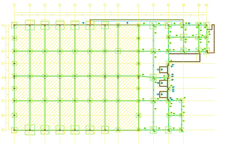
These new arrangements necessitate verification of the bearing capacity (SLS/ULS) and estimation of absolute and differential settlements based on these new foundations embedded in the fill layer as shown in Figure 1.

These investigations consist of static vertical driving into the ground of a standardized conical point, carried out at a controlled constant speed of 2 cm/s, without shock, vibration or rotation. The force is transmitted by a string of connected rods. The test allows continuous, real-time acquisition of three key parameters depending on depth:
Peak resistance  , measuring resistance to static penetration;
The unitary lateral friction  , mobilized on the cylindrical sleeve;
The pore pressure u, measured at the pressure sensor in a saturated environment.
Rigorously carried out according to the NF EN ISO 22476-1 standard and 5 and 6, these surveys make it possible to use graphic profiles called penetrograms for:
Determine the fine stratigraphy and the succession of geotechnical horizons;
Evaluate the spatial homogeneity of the layers or detect possible anomalies;
Deduce the geotechnical properties and intrinsic characteristics of the soils crossed (identification, rigidity, drained or undrained behavior).
The comparative compilation of peak resistance profiles induces a relatively homogeneous underlying horizon. The formalized geotechnical model makes it possible to establish characteristic values per lithological horizon from geometric averages.
The foundations are justified according to standard NF P94-261, the application standard of Eurocode 7. The load reductions provided are made up of vertical and horizontal forces (permanent load G and operating load Q). The calculations were carried out with the Fondsup module of the FOXTA software for the soles 7 et 8. The lifting capacity is checked using the inequality below:
 | (1) |
 : Calculation value of the vertical force to be taken up by the foundation (including weight of the foundation)
 : Initial weight of the earth at the base of the foundation (after work). A density of 18 kN/m3 was considered.
 : Calculation value of the net resistance of the ground
In order to ensure the slip resistance of a sole undergoing horizontal forces, it is necessary to check non-slip for fundamental, accidental ULS
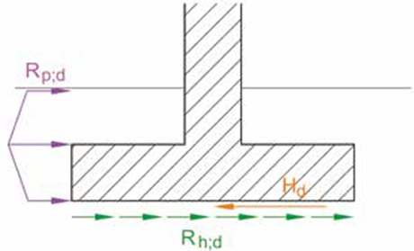
At ultimate limit states (ULS), for long-term, transient, and accidental design situations. 9. The sliding stability of shallow foundations is justified with respect to all load cases and combinations of actions by verifying the following inequality as shown in Figure 2:
 | (2) |
Where the variables are defined according to the sliding resistance components illustrated [above/below]:
 : Design value of the component of the action parallel to the contact plane of the foundation.
 : Design value of the passive resistance (frontal or tangential) of the ground. This favorable component can only be integrated if the footing displacements are compatible with the kinematics of the supported structure. Given the low mobilization of the passive resistance near the free surface, its value is frequently considered negligible.
 : Design value of the sliding resistance at the foundation-soil interface. Under drained conditions, its determination is carried out according to the following formula:
 | (3) |
 denotes the design value of the ultimate sliding resistance;
 represents the design value of the vertical action transmitted to the ground by the shallow foundation, determined for each combination of actions generating the concomitant component
  ;
;
 corresponds to the partial factor associated with the sliding resistance, the regulatory value of which is set at 1.1 for permanent and transient situations (fundamental ULS) and at 1.0 for accidental situations (accidental ULS);
 is the model coefficient related to the evaluation of the ultimate resistance to sliding, introduced with a value of 1.1;
 constitutes the characteristic value of the friction angle at the footing-soil interface (according to Calculation Approach 2,
 .
.
For cast-in-place foundations, the design value .. can be considered equivalent to the effective friction angle at the critical state  . For smooth precast foundations, it is conventionally set at

The evaluation of the absolute settlement s is carried out by penetrometer testing, according to the following expression:
 | (4) |
Where
 | (5) |
 | (6) |
 is the shape factor for shallow foundations:
1.25 for square foundations
1.75 for strip footings with L > 10 B
 is the effective initial vertical stress at the foundation level
Where t denotes the service life, expressed in years (t = 10 years according to FONDSUP specifications), and  represents the influence factor for deformations, determined in accordance with Annex I of standard NF P 94-261.
E=2.5  for asymmetrical foundations (circular and square)
E=3.  for strip foundations with plane deformation
Figure 2: Diagram illustrating the sliding resistance of a footing (NF P94-261)
The Load Transfer mechanism is illustrated in Figure 2.

The initial loads exclude the self-weight of the foundation blocks, which was factored in by considering a wet/flooded concrete unit weight of 25 kN/m³. 11 The footings in "Area 1" (rows 1 to 9) are placed on the existing fill. They support a fill and structural slab with a nominal thickness of approximately 0.80 m. Conversely, the foundations in "Area 2" and "Area 3" (extension, rows 1 to 003) have deep anchorage in the subsoil, under a cover height (fill of required compaction and slab) of approximately 2.50 m.
The geometric characteristics of the shallow foundations are taken from the formwork plans in the Appendix. The limit state verifications were conducted based on this projected geometry. The combinations of envelope actions selected for the design of each footing correspond to the following restrictive criteria:
Hmax: Maximization of shear force (maximum horizontal load).
Nmin: Minimization of axial force (minimum vertical load, critical for uplift and sliding).
Nmax: Maximization of axial force (maximum vertical load, critical for bearing capacity).
The quantification of actions at the Ultimate Limit State (ULS) applies the regulatory 12. The factor G = 1.35 for permanent and collateral loads, and a factor Q = 1.50 for the determining variable action. Associated variable actions (live loads or wind loads) are included with their combination coefficient reduced to 1.0.
The synthesis of the design combinations and the associated geotechnical justifications are listed in Table 2 (Area 1) and Table 3 (Areas 2 & Area 3). The complete calculation notes are provided in Appendix 5. Finally, sliding stability at the soil-structure contact plane was validated using an interface friction angle of 30° 13.
- The Unit Weight, 
 | (7) |
Where  = water unit weignt
- Permeability, k(m/s)
 | (8) |
 | (9) |
- 
 | (10) |
 | (11) |
- Young’s Modulus, Es (MPa)
 | (12) |
Applicable only to 
- Relative Density, 
 | (13) |
Applicable only to 
- State Parameter 
 | (14) |
- Drained Friction Angle, 
applicable only to 
1-D Constrained modulus, M(MPa)
 | (15) |
 | (16) |
 |
- Small strain shear Modulus, Go (MPa)
 | (17) |
Shear Wave Velocity, Vs(m/s)
 | (18) |
Undrained peak shear strength,  (kPa)
(kPa)
 | (19) |
 | (20) |
Remolded undrained shear strength 
 | (21) |
 | (22) |
Or user defined
 | (23) |
 |
- In situ Stress Ratio, 
 | (24) |
 |
- Soil sensitivity, 
 | (25) |
 |
- Peak Friction Angle, 
 | (26) |
Table 1 presents the stratigraphic profile of the soil as well as the evolution of its geotechnical properties with depth. In general, tip resistance qc increases significantly with depth, reflecting the typical behavior of a granular medium subject to confinement effects. However, a local inflection is observed between -4.15 m and -5.37 m, characterized by a decrease in qc (from 20,800 to 16,100 kPa). This localized drop suggests the presence of a looser lens or one with a higher silt content, located immediately above the distinct sandy formation. Furthermore, the marked discontinuity in the values of the effective volumetric weight allows us to precisely locate the level of the water table at a depth of 2.46 meters.
Table 2 highlights an increase in the mechanical properties of the medium with depth. This phenomenon is attributable to confining pressure or the transition to a sounder substrate. The permeability values (k), ranging from moderate to high, are characteristic of clean sands, gravels, or a fractured rock mass. The maintenance of this permeability with depth indicates the persistence of an interconnected network of pores or fissures. Furthermore, the high values of the internal friction angle characterize a dense, highly interlocking, or rocky material. In summary, this geotechnical profile corresponds either to a very dense granular soil or, more likely, to a weathered and fractured rock mass at the surface that becomes denser with depth. The absence of cohesion c'=0, combined with high friction, confirms purely frictional behavior 14
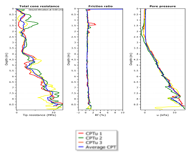
Figure 3 presents the profiles of tip resistance, sleeve friction, and pore water pressure measured using a piezocone (CPTu) versus depth. Between 0 and 3 m, tip resistance and pore water pressure remain low, before increasing exponentially up to the maximum depth of 8.63 m. This trend highlights an increase in soil bearing capacity with depth. In contrast, sleeve friction remains relatively constant throughout the profile, suggesting overall homogeneity of the sedimentary matrix

The ultimate limit state (ULS/SLS) verifications are satisfied for the selected footing dimensions and recommended anchorage depths. These depths are set at approximately 0.8 m from the finished elevation in Area 1 and approximately 2.5 m in Areas 2 and 3.
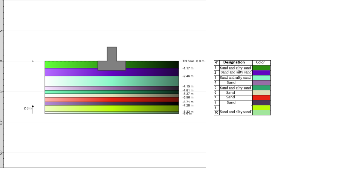
The calculated absolute settlements in this configuration are negligible, with maximum values less than 1 cm. Consequently, the induced differential settlements remain acceptable. Due to the predominantly granular (sandy) nature of the soil horizons, most of these settlements will be instantaneous and will occur during the construction phase, before the structures are handed over. The stratigraphy of the soil foundation to 8,6m depth is shown on Figure 4.

Under centered vertical loading, the minimum allowable design stress (SLS) for any 1.0 m wide footing supported on the backfill is 200 kPa (or 325 kPa at the ultimate limit state -ULS). Although the effect of confinement increases the bearing capacity of anchored foundations, it is recommended to limit the allowable stress to 300 kPa at the SLS (or approximately 492 kPa at the ULS) for an anchorage at -2.5 m below the finished slab level.
Table 3 compares the applied loads with the soil's bearing capacity across the structure's various axes.
For all axes studied, the applied design vertical load (Vd) remains well below the soil's design resistance (Rvd), thereby ruling out any risk of punching shear failure. Furthermore, the soil's shear strength is sufficient to resist horizontal sliding of the footings under oblique or climatic loads (wind).
At the Serviceability Limit State (SLS), calculated absolute settlements are less than 10 mm. This minimal magnitude eliminates the risk of structural damage due to cracking. Spatial load analysis indicates that the structure's maximum loads are concentrated on axes H01 and H002, whereas axes B00 and C00 correspond to the least heavily loaded zones.
In conclusion, the foundation block exhibits excellent bearing capacity relative to the design loads. The maximum differential settlement between axes, estimated at 7.8 mm, is insufficient to cause angular distortions that would compromise the building's long-term integrity.
Following the geotechnical execution study (G3 mission), which focused on the design of the shallow foundations o n the existing platform embankment and the dimensioning of the anchored footings for the quay extension, the operational conclusions are as follows:
a) Lithostratigraphy and mechanical properties
The soil profile reveals a surface horizon of sandy-silty embankment (thickness varying from 1.3 m to 1.5 m), overlying a substratum of fine sands with a low to medium degree of cleanliness. In terms of compaction, the upper horizon (from the surface down to -3.0 m) exhibits a medium critical density, while the underlying layers are highly densified.
b) Foundation Design and Deformations
Under the applied load combinations, the Ultimate Limit State (ULS/SLS) verifications of the proposed footings—detailed in Table 2 (Area 1) and Tables 3 (Area 2 & Area 3) are formally validated.
The minimum required geotechnical embedment is set at 0.8 m below the finished level for Area 1, and at 2.5 m for Areas 2 & 3. The absolute settlements calculated under these configurations are highly negligible, with a maximum settlement of less than 10 mm, thus guaranteeing the acceptability of differential settlements. Due to the purely granular (sandy) nature of the soil matrix, the major component of these deformations will be instantaneous and will manifest itself during the construction phase 15
c) Bearing capacities and allowable stresses
Under the action of a centered vertical load, the minimum effective design stress for a 1 m wide footing embedded in the backfill is 200 kPa at the SLS (i.e., 325 kPa at the ULS). For foundations anchored at -2.5 m relative to the extension platform, although the theoretically higher bearing capacity, the design stress is intentionally limited to a pragmatic value of 300 kPa at the SLS (i.e., approximately 492 kPa at the ULS).
d) Construction monitoring and quality assurance
Finally, it is essential to implement a continuous quality assurance protocol during the placement of backfill, concrete, and inclusions to guarantee the conformity of the calculation parameters used in the geotechnical model and to ensure the long-term durability of the structure.
This study on Cotonou Airport demonstrates that a geotechnical approach combining piezocone tests and numerical modeling using FOXTA allows for the design of robust shallow foundations adapted to the local sandy soils. The rigorous application of the NF P94-261 standard guarantees instantaneous settlements of less than 10 mm, thus ensuring the stability and long-term durability of this critical infrastructure. Compared to traditional methods, the in-situ piezocone test method allows for:
The precise characterization of fine and stratified soils by identifying intercalations of loose or compressible soils that are invisible during conventional drilling. Optimization of the bearing capacity and settlement calculations is made possible by accessing the preconsolidation stress and the soil deformation modulus, which allows for the identification of the extremely strict differential settlement criterion to prevent cracking. Controlling the risks of liquefaction and overpressure allows for the containment of vibrations induced by heavy aircraft traffic and the estimation of settlement rates under future structures. Furthermore, the piezocone-based technique ensures coverage of large areas in record time without generating debris, reduces geotechnical uncertainties to achieve excessive safety factors, and optimizes the thickness and reinforcement of foundation footings, all of which ensure cost and loss reduction.
The limitations of this piezocone geotechnical study (CPTu) are as follows:
- the intrinsic limitations of the CPTu tool. The CPTu does not collect soil samples. Key geotechnical parameters (such as the friction angle, undrained cohesion, or the deformation modulus are extrapolated via empirical correlations. These relationships may lack precision if they are not calibrated with site-specific laboratory tests (triaxial, oedometer tests).
- The sensitivity of the pore pressure measurement (u2), particularly the quality of saturation of the piezocone filter, is crucial. Poor saturation in alternating soil layers (sand/clay) can distort calculations and impact bearing capacity.
- The specific characteristics of airport loads. CPTu measures primarily static properties during tip penetration at a constant speed (2 cm/s). However, an airport environment is subjected to heavy cyclic loads (aircraft landings and taxiing) that induce soil fatigue and cyclic pore pressures that the standard CPTu profile cannot fully predict without complementary dynamic tests (such as SCPTu for shear wave velocity.
- Numerical models based on in situ tests such as CPTu, by sometimes simplifying soil behavior to the extreme or by mathematically forcing convergence towards an optimal solution, can generate several critical risks. In our study context, it is possible to test several models or tests, for effective and sustainable decision-making.
Any acknowledgement is required
| [1] | T. Lunne, P. K. Robertson, and J. J. M. Powell "CONE-PENETRATION TESTING IN GEOTECHNICAL PRACTICE". Soil Mechanics and Foundation Engineering, Vol. 46, No. 6, 2009. | ||
| In article | View Article | ||
| [2] | DOSSOU, K. M. R. and GLÉHOUENOU-DOSSOU, B., (2007). The vulnerability to climate change of Cotonou (Ben99in): the rise in sea level. International Institute for Environment and Development (IIED).Vol 19(1): 65–79. | ||
| In article | View Article | ||
| [3] | Boukari,M., Viaene, P. and Azonsi, F. (2028). Three-dimensional modelling of a coastal sedimentary basin of southern Benin (West Africa). Applied Groundwater Studies in Africa, 1st Edition. | ||
| In article | |||
| [4] | ASTM International. (2020). ASTM D5778-20 Standard test method for electronic friction cone and piezocone penetration testing of soils. ASTM International. doi.org. | ||
| In article | |||
| [5] | NF P 94-262, norme d'application française de l'Eurocode 7 pour les fondations profondes. | ||
| In article | |||
| [6] | TERRASOL, 2020. Manuel d'utilisateur Foxta v4 – Partie C.2: Notice technique FONDPROF v4.x. Édition de juillet 2020. Paris: TERRASOL. | ||
| In article | |||
| [7] | Terrasol. (2021). FOXTA (Version 4) [Fondsup module] [Computer software]. https://terrasol.setec.fr/logiciels/foxta/. | ||
| In article | |||
| [8] | Mayne, P.W. (2014). KN2: Interpretation of geotechnical parameters from seismic piezocone tests. Proceedings, 3rd International Symposium on Cone Penetration Testing (CPT'14, Las Vegas), ISSMGE Technical Committee TC 102, Edited by P.K. Robertson and K.I. Cabal: p 47-73. Three-dimensional modelling of a coastal sedimentary basin of southern Benin (West Africa). Applied Groundwater Studies in Africa,1st Edition. | ||
| In article | |||
| [9] | EN 1997-1: European Committee for Standardization. (2004). Eurocode 7: Geotechnical design - Part 1: General rules (EN 1997-1:2004). CEN European Committee for Standardization. | ||
| In article | |||
| [10] | NF P94-261 (2013) Justification des ouvrages géotechniques. Normes d’application nationales de l’Eurocode 7, Fondations superficielles. 130 P. | ||
| In article | |||
| [11] | Computers and Structures, Inc. (2026). CSI SAFE (Version 24) [Computer software]. csiamerica.com. | ||
| In article | |||
| [12] | EN 1990 (2002). European Committee for Standardization. (2002). Eurocode: Basis of structural design. | ||
| In article | |||
| [13] | Henning, M., ., ., ., (2025). Ring penetrometer for interface shear testing on sand under low-stress conditions. Geotechnique (2025) 75 (10): 1295–1308. | ||
| In article | View Article | ||
| [14] | Viana da Fonseca, A., Buttling, S., & Coutinho, R. Q. (2012). Foundations: Shallow and deep foundations, unsaturated conditions, heave and collapse, monitoring and proof testing. In B. B. K. Huat, D. G. Toll, & A. Prasad (Eds.), A Handbook of Tropical Residual Soil Engineering (pp. 283–412). CRC Press / Taylor & Francis Group. | ||
| In article | View Article | ||
| [15] | Kristić, I., , V.,, P., (2017). Direct method for determination of shallow foundation settlements. Građevinar. | ||
| In article | |||
Published with license by Science and Education Publishing, Copyright © 2026 Kassa Issifou Mounou Sambieni
 This work is licensed under a Creative Commons Attribution 4.0 International License. To view a copy of this license, visit
http://creativecommons.org/licenses/by/4.0/
This work is licensed under a Creative Commons Attribution 4.0 International License. To view a copy of this license, visit
http://creativecommons.org/licenses/by/4.0/
| [1] | T. Lunne, P. K. Robertson, and J. J. M. Powell "CONE-PENETRATION TESTING IN GEOTECHNICAL PRACTICE". Soil Mechanics and Foundation Engineering, Vol. 46, No. 6, 2009. | ||
| In article | View Article | ||
| [2] | DOSSOU, K. M. R. and GLÉHOUENOU-DOSSOU, B., (2007). The vulnerability to climate change of Cotonou (Ben99in): the rise in sea level. International Institute for Environment and Development (IIED).Vol 19(1): 65–79. | ||
| In article | View Article | ||
| [3] | Boukari,M., Viaene, P. and Azonsi, F. (2028). Three-dimensional modelling of a coastal sedimentary basin of southern Benin (West Africa). Applied Groundwater Studies in Africa, 1st Edition. | ||
| In article | |||
| [4] | ASTM International. (2020). ASTM D5778-20 Standard test method for electronic friction cone and piezocone penetration testing of soils. ASTM International. doi.org. | ||
| In article | |||
| [5] | NF P 94-262, norme d'application française de l'Eurocode 7 pour les fondations profondes. | ||
| In article | |||
| [6] | TERRASOL, 2020. Manuel d'utilisateur Foxta v4 – Partie C.2: Notice technique FONDPROF v4.x. Édition de juillet 2020. Paris: TERRASOL. | ||
| In article | |||
| [7] | Terrasol. (2021). FOXTA (Version 4) [Fondsup module] [Computer software]. https://terrasol.setec.fr/logiciels/foxta/. | ||
| In article | |||
| [8] | Mayne, P.W. (2014). KN2: Interpretation of geotechnical parameters from seismic piezocone tests. Proceedings, 3rd International Symposium on Cone Penetration Testing (CPT'14, Las Vegas), ISSMGE Technical Committee TC 102, Edited by P.K. Robertson and K.I. Cabal: p 47-73. Three-dimensional modelling of a coastal sedimentary basin of southern Benin (West Africa). Applied Groundwater Studies in Africa,1st Edition. | ||
| In article | |||
| [9] | EN 1997-1: European Committee for Standardization. (2004). Eurocode 7: Geotechnical design - Part 1: General rules (EN 1997-1:2004). CEN European Committee for Standardization. | ||
| In article | |||
| [10] | NF P94-261 (2013) Justification des ouvrages géotechniques. Normes d’application nationales de l’Eurocode 7, Fondations superficielles. 130 P. | ||
| In article | |||
| [11] | Computers and Structures, Inc. (2026). CSI SAFE (Version 24) [Computer software]. csiamerica.com. | ||
| In article | |||
| [12] | EN 1990 (2002). European Committee for Standardization. (2002). Eurocode: Basis of structural design. | ||
| In article | |||
| [13] | Henning, M., ., ., ., (2025). Ring penetrometer for interface shear testing on sand under low-stress conditions. Geotechnique (2025) 75 (10): 1295–1308. | ||
| In article | View Article | ||
| [14] | Viana da Fonseca, A., Buttling, S., & Coutinho, R. Q. (2012). Foundations: Shallow and deep foundations, unsaturated conditions, heave and collapse, monitoring and proof testing. In B. B. K. Huat, D. G. Toll, & A. Prasad (Eds.), A Handbook of Tropical Residual Soil Engineering (pp. 283–412). CRC Press / Taylor & Francis Group. | ||
| In article | View Article | ||
| [15] | Kristić, I., , V.,, P., (2017). Direct method for determination of shallow foundation settlements. Građevinar. | ||
| In article | |||